3. Fasten the FSO-xx onto slot 3 of the BCU control unit [A41] with four screws.
Electrical installation 125
Mechanical installation of an FSO-xx safety functions module
This procedure describes the mechanical installation of an FSO-xx safety functions
module onto the inverter control unit. (The FSO-xx can alternatively be installed beside the
control unit, which is the standard with factory-installed FSO-xx modules. For instructions,
see the FSO-xx manual.)
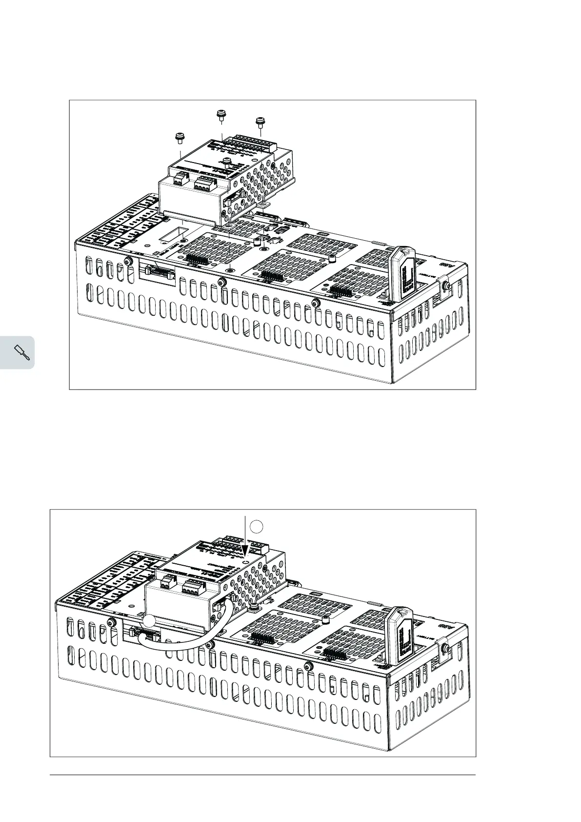
1. Fasten the module onto slot 3 of the inverter control unit (A41) with four screws.
4. Tighten the FSO-xx electronics grounding screw.
Note: The screw tightens the connections and grounds the module. It is essential for
fulfilling the EMC requirements and for proper operation of the module.
5. Connect the FSO-xx data cable between FSO-xx connector X110 and BCU-x2 connector
X12.
6. To complete the installation, refer to the instructions in the User’s manual delivered with
the FSO-xx.
126 Electrical installation
2. Tighten the FSO-xx electronics grounding screw.
3. Connect the FSO-xx data cable between FSO-xx connector X110 and to BCU-x2
connector X12.
Wiring of optional modules
See the appropriate optional module manual for specific installation and wiring
instructions.
5
4
82 Electrical installation

 Loading...


