holder; those that do not require the installation of an FDPI-02 module (available separately).
For further information, see the hardware description and FDPI-02 diagnostics and panel
interface user’s manual (3AUA0000113618 [English]).
The maximum allowed length of the cable chain is 100 m (328 ft).
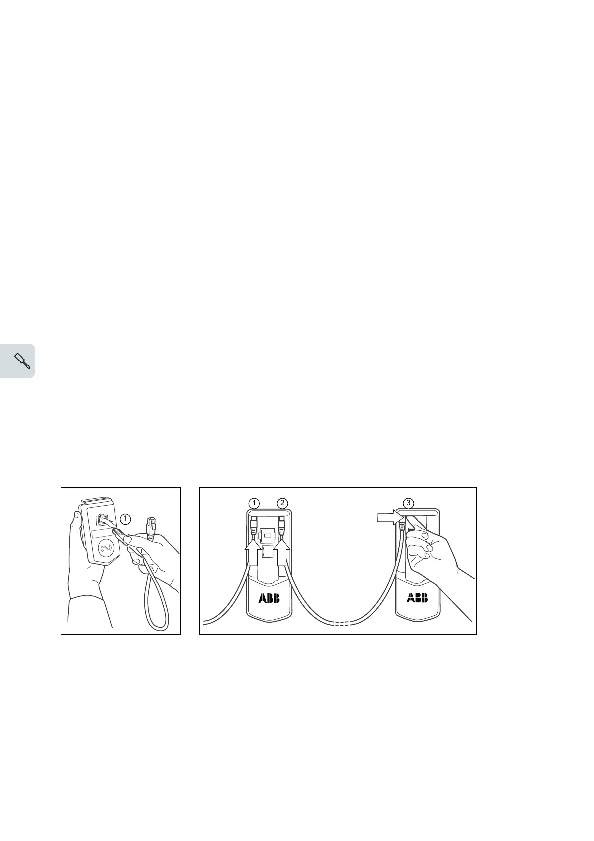
1. Connect the panel to one drive using an Ethernet (for example Cat 5e) cable.
• Use Menu - Settings - Edit texts - Drive to give a descriptive name to the drive
•
Use parameter 49.01* to assign the drive with a unique node ID number
• Set other parameters in group 49* if necessary
•
Use parameter 49.06* to validate any changes.
*The parameter group is 149 with supply (line-side), brake or DC/DC converter units.
Repeat the above for each drive.
2. With the panel connected to one unit, link the units using Ethernet cables.
3. Switch on the bus termination on the drive that is farthest from the control panel in the
chain.
• With drives that have the panel mounted on the front cover, move the terminating
switch into the outer position.
• With an FDPI-02 module, move termination switch S2 into the TERMINATED
position.
Make sure that bus termination is off on all other drives.
4. On the control panel, switch on the panel bus functionality (Options - Select drive - Panel
bus). The drive to be controlled can now be selected from the list under Options - Select
drive.
If a PC is connected to the control panel, the drives on the panel bus are automatically
displayed in the Drive composer tool.
With twin connectors in the control panel holder:
88 Electrical installation

 Loading...


