24 Hardware description
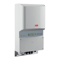
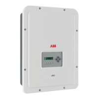
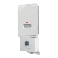
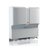
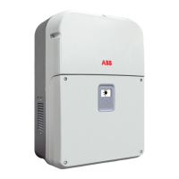
The inverter has three models:
After the inverter is installed and commissioned, it operates automatically:
1. The inverter starts when there is sufficient daylight for the PV modules to generate
an input voltage above the minimum operating limit.
2. The inverter verifies the status of the power line and then switches to the normal
operating mode.
3. The inverter feeds current to the power line, and monitors both the PV arrays
(DC) and power line (AC).
4. When the daylight is not sufficient to generate an input voltage below the
minimum operating limit, the inverter goes to the stand-by mode. The inverter
uses the AC power supply to keep the control unit on.
5. When the input voltage is lower than the threshold input voltage, the inverter goes
to the sleep mode. It uses the AC power supply to keep the control unit on.
Model Description
PRO-33.0-TL-OUTD-400
(Standard model)
1 DC input connection to an external string combiner box. The
connection uses screw terminals.
PRO-33.0-TL-OUTD-S-400
(-S model)
In addition to the standard model specification, it has an
integrated DC switch which isolates the PV array from the
electrical grid.
PRO-33.0-TL-OUTD-SX-400
(-SX model)
This model has an integrated string combiner box with:
• An integrated DC switch, which isolates the PV array from
the electrical grid.
• 8 string inputs with PV quick connectors. The connectors
have sealing caps.
• Monitored string fuses (16 pcs) for both positive and negative
inputs.
• String current monitoring with configurable alarm limit.
• Replaceable monitored surge protection device for DC input,
Type II.
Accessories required for the -SX model:
• 3N750080000A, SUNCLIX DC cable connector kit, 8 pcs
SUNCLIX DC+ connector and 8 pcs SUNCLIX DC-
connector, or
• Phoenix Contact SUNCLIX: DC+ connector PV-CF-S
(1774674) and DC- connector PV-CF-M (1774687)
 Loading...


