148
ABOV Semiconductor Co., Ltd.
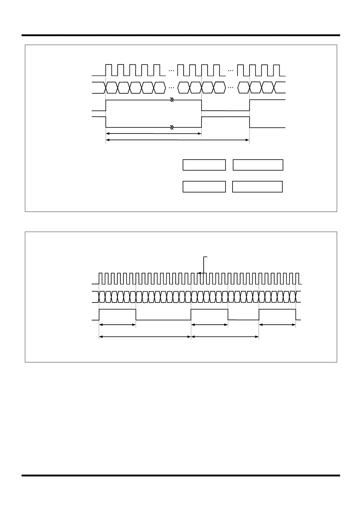
Figure 11.36 Example of PWM at 4 MHz
Figure 11.37 Example of Changing the Period in Absolute Duty Cycle at 4 MHz
Update period & duty register value at once
The period and duty of PWM comes to move from temporary registers to T4PPRH/L (PWM Period Register) and
T4ADRH/L/T4BDRH/L/T4CDRH/L (PWM Duty Register) when always period match occurs. If you want that the period
and duty is immediately changed, the UPDT bit in the T4PCR1 register must set to ‘1’. It should be noted that it needs
the 3 cycle of timer clock for data transfer in the internal clock synchronization circuit. So the update data is written
before 3 cycle of timer clock to get the right output waveform.
T4CR = 03
H
(2 us)
T4PPRH = 00
H
T4PPRL = 0E
H
T4ADRH = 00
H
T4ADRL = 05
H
Duty Cycle
(1+05
H
)X2 us = 12 us
Duty Cycle
(1+05
H
)X2 us = 12 us
Duty Cycle
(1+05
H
)X2 us = 12 us
Period Cycle
(1+0E
H
)X2 us = 32 us 31.25 kHz
Period Cycle
(1+0A
H
)X2 us = 22 us 45.5 kHz
Duty Cycle(1+80
H
)X250ns = 32.25us
Period Cycle(1+3FF
H
)X250ns = 256us 3.9kHz
T4CR = 00
H
(f
XIN
)
T4PPRH = 03
H
T4PPRL = FF
H
T4ADRH = 00
H
T4ADRL = 80
H

 Loading...


