149
ABOV Semiconductor Co., Ltd.
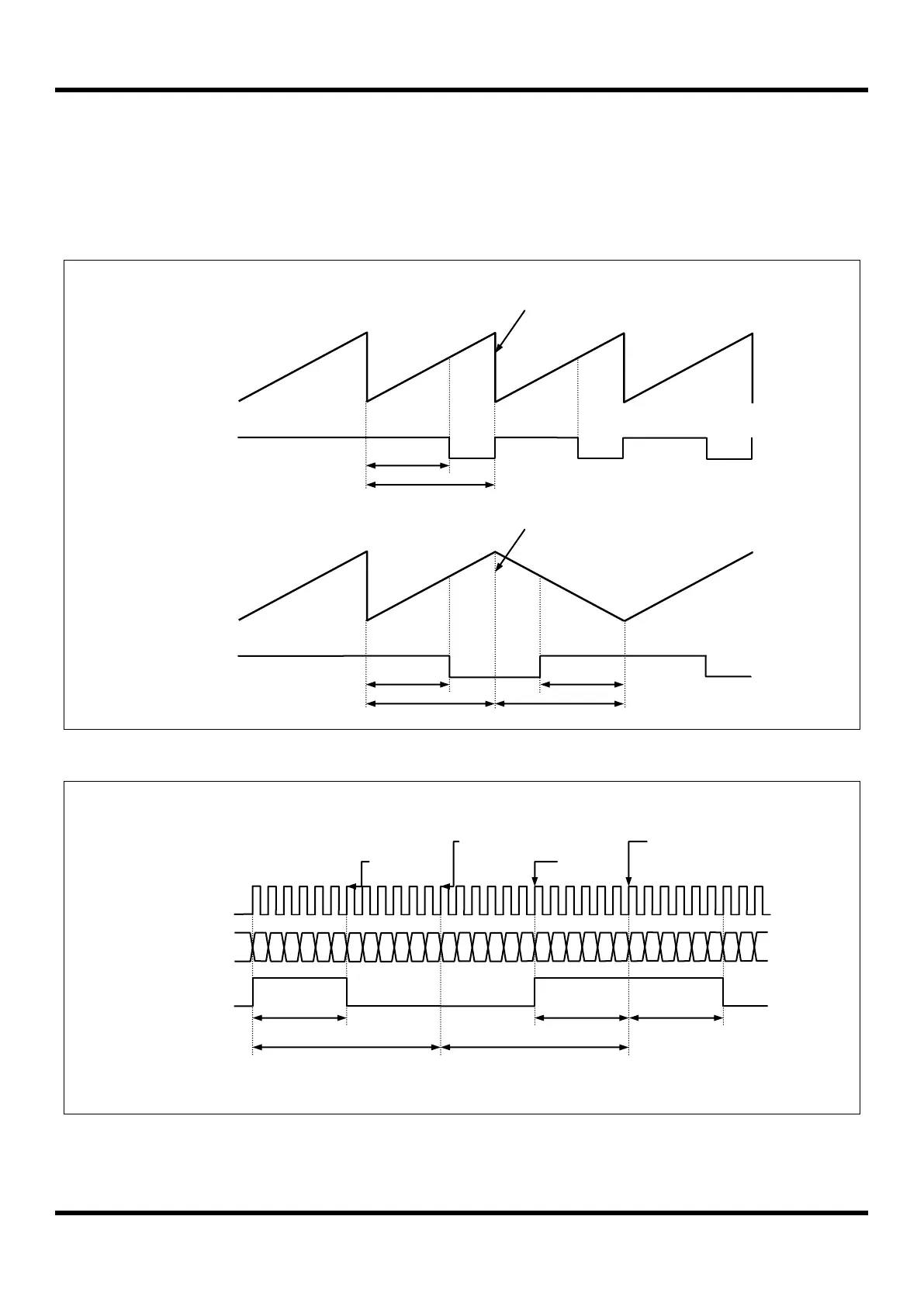
Phase correction & Frequency correction
On operating PWM, it is possible that it is changed the phase and the frequency by using BMOD bit (back-to-back
mode) in T4PCR1 register. (Figure 1.38, Figure 11.39, Figure 11.40 referred)
In the back-to-back mode, the counter of PWM repeats up/down count. In fact, the effective duty and period becomes
twofold of the register set values. (Figure 1.38, Figure 11.39 referred)
Figure 11.38 Example of PWM Output Waveform
Figure 11.39 Example of PWM waveform in Back-to-Back mode at 4 MHz
T4CR = 03
H
(2 us)
T4PPRH = 00
H
T4PPRL = 0B
H
T4ADRH = 00
H
T4ADRL = 05
H
Duty Cycle
(1+05
H
)X2 us = 12 us
Duty Cycle
(1+05
H
)X2 us = 12 us
Duty Cycle
(1+05
H
)X2 us = 12 us
Period Cycle
(1+0B
H
)X2 us = 26 us 38.46 kHz
Period Cycle
(1+0B
H
)X2 us = 26 us 38.46 kHz

 Loading...


