153
40.24 ref 1 /ref 2 selection at PID disable
0: '40.23' setting value ----- Initial value
1: '40.22' setting value
2: DI1
3: DI2
4: DI3
5: DI4
6: DI5
7: DI6
8: DI7
9: DI8
Configures the selection between frequency references 1 and 2
Set 0:
'40.23' setting value
The frequency is used by
'40.23'(ref 1 /ref 2 combination at PID disable)
set value
Set 1:
'40.22' setting value
The frequency is used by
'40.22'(ref source 2 at PID disable)
Set 2~9 : DI1~ DI8
If the digital input which is selected has OFF, it will applied by ref 1
If the digital input which is selected has ON, it will applied by ref 2
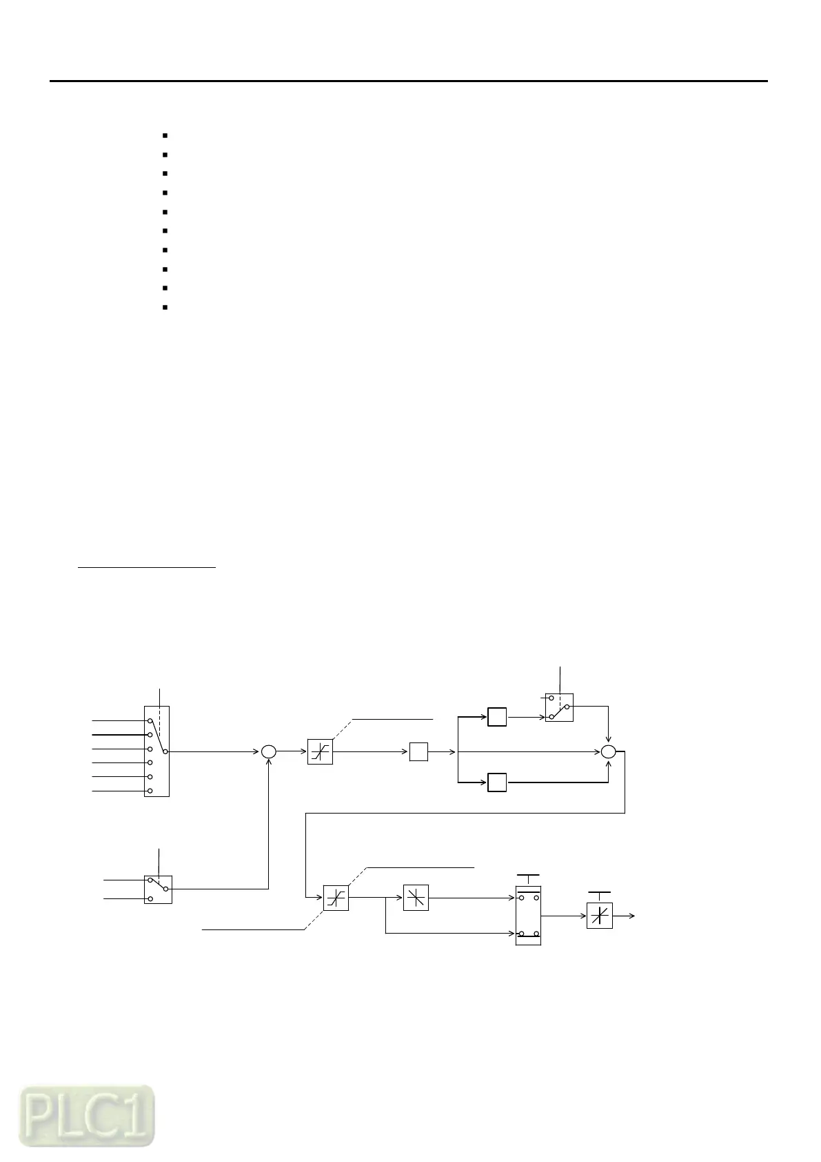
PID Control Diagram
The overall PID control diagram with respective parameters is shown in below
+
0: AI1 (O)
1: AI2 (OI)
2: Keypad
3: Modbus
4: Fieldbus
5: UP/DOWN
40.03 (PID reference source)
40.04 (PID feedback source)
-
LIMIT
+
+
+
40.09 (PID output high limit)
Limit
40.11 (PID output invert)
Invert
0
P
I
D
40.07 (D gain)
40.06 (I gain)
40.05 (P gain)
Gain
Gain
Gain
40.12 (PID scale factor)
Scale
40.18 (PID output monitor)
40.02 (PID reference)
Target reference
0: AI1 (O)
1: AI2 (OI)
Feedback
40.19 (PID integral reset source)
clear
40.10 (PID output low limit)
40.08 (PID Err limit)