21
4.1.2 Wiring precaution
1) Main Power Terminals: R(L1), S(L2), T(L3)
Connect the main power terminals (R(L1), S(L2) and T(L3)) to the power supply through
an electromagnetic contactor or an earth-leakage breaker. These devices isolate the
utility power supply from the VFD and prevent the spread of damage.
This unit is designed to be used on a three-phase power supply. If using on a single
phase power supply, please contact ADT for proper sizing.
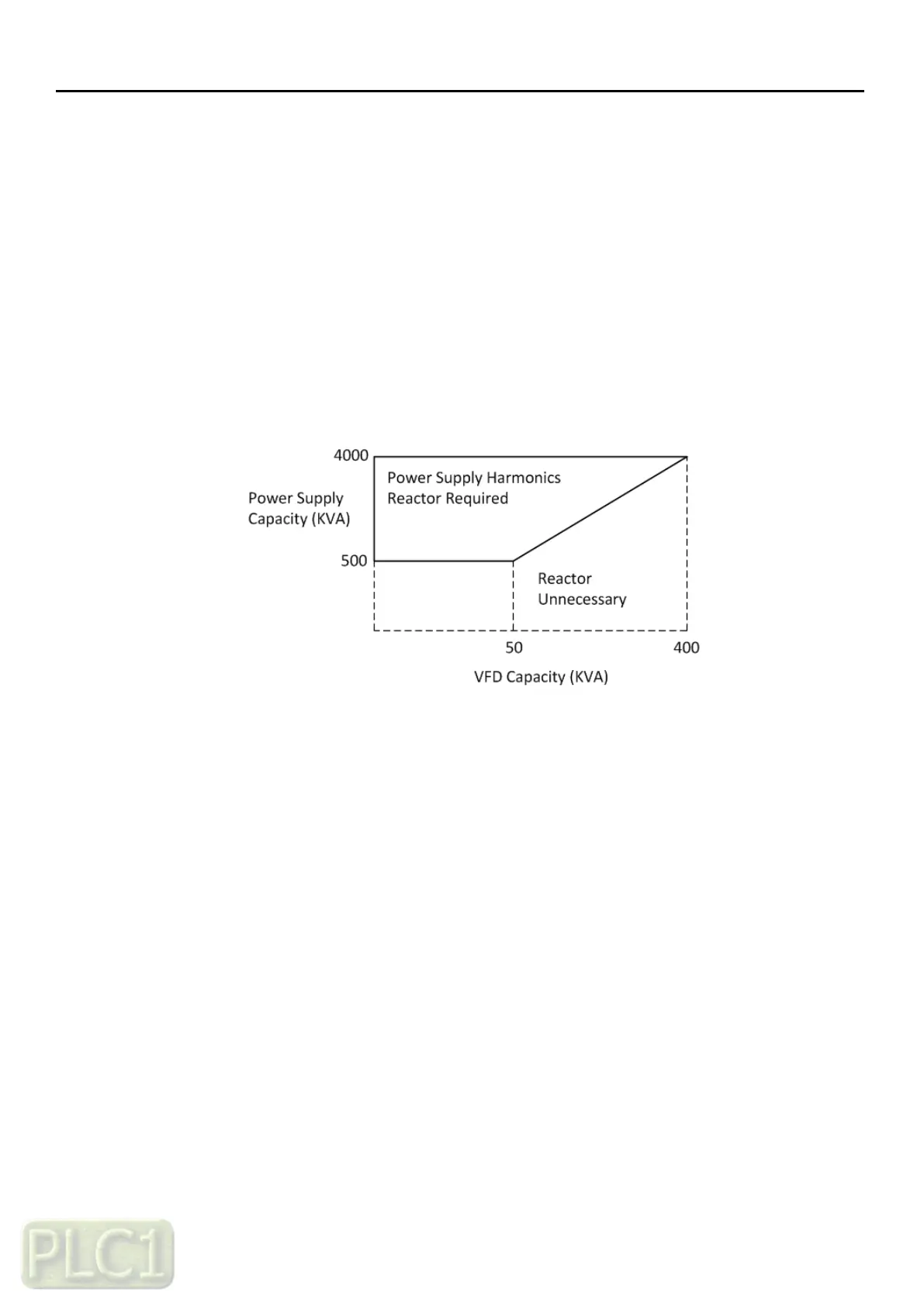
Do not operate under the following conditions.
- Unbalanced power supply voltage more than 3%
- Power supply capacity more than 10 times of the capacity of VFD and case beyond
500kVA.
- Turning on/off the power supply more than three times in one minute,
It could be damaged the recharge circuit of the VFD.
2) VFD Output Terminals: U(T1), V(T2), W(T3)
Make sure to use a heavier gauge wire when you have long motor leads.
This will help to reduce the voltage drop.
Do not install power factor correction capacitors or a surge absorber to the output of
the VFD. The VFD will trip or sustain damage to the output transistors.
If the motor cable length is more than 65 feet, it is possible that a surge voltage will
be generated and may damage the motor. This is due to phenomena called "Reflective
Wave". Install a dv/dt filter in front of the motor to protect it.
In the case of two or more motors on the output of a VFD, install an independent
overload protection device for each motor. Set the rated current value of the overload
device to 1.1 times the motor rated current.