22
3) Regenerative Braking Unit Terminals: P, N ( >= 30kW(40HP) Units)
VFDs rated greater than and equal to 30KW (40HP) do not contain an internal BRD
circuit. If regenerative braking is going to occur, then an external BRD circuit (Option)
is required along with a resistor. (Option)
Connect external regenerative braking unit terminals (P,N)
to terminals (P,N) on the VFD.
The braking resistor is then wired into the External BRD board,
not directly to the VFD.
The cable length between the VFD and the BRD board, BRD board and the resistor,
should be less than 16 feet and twist the connecting wires to reduce inductance.
4) Earth Ground: G
Make sure that you securely ground the VFD and motor
for prevention of electric shock.
The VFD and motor must be connected to an appropriate safety earth ground and
follow all local electrical codes.
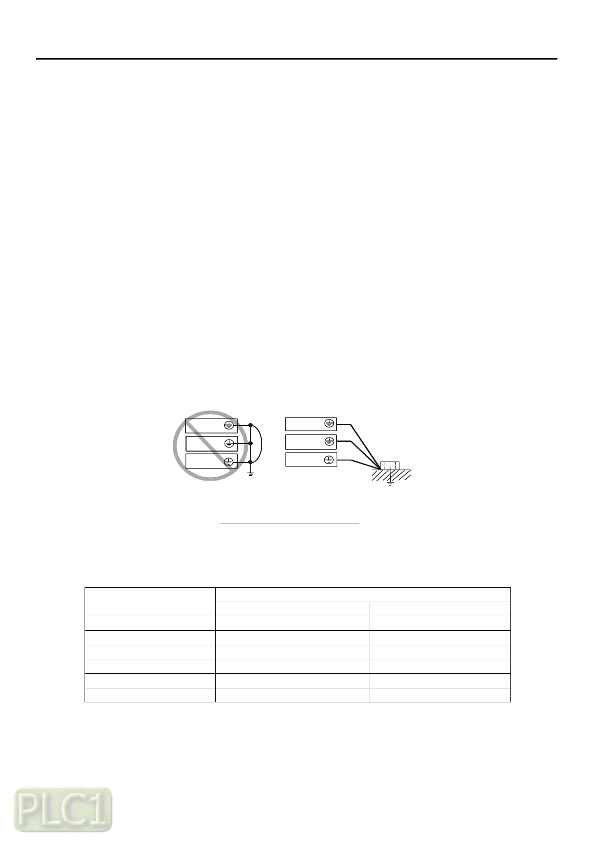
In case connecting 2 or more VFDs, use caution not to create a ground loop situation
which may cause the VFD to malfunction. Use a star configuration grounding
technique.
Earth Ground (G) Connection
Grounding wire should be as short as possible and should be connected
to the ground point as near as possible to the VFD.
Grounding Wire Size (mm
2
/kcmil)
INVERTER
INVERTER
INVERTER
INVERTER
INVERTER
INVERTER