29
4.1.5 Control terminal line diagram (Basic I/O terminal block)
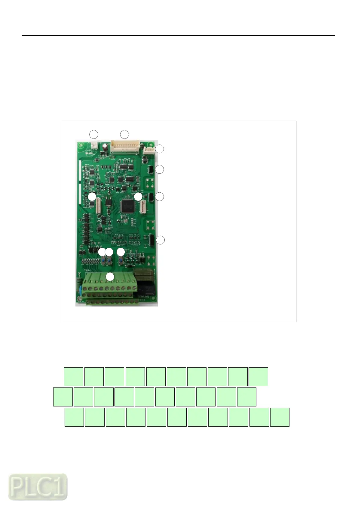
1) External control connection terminals
The layout of external control connection terminals of the drive is shown below.
2
3
1
1. +24Vdc input connector
2. Logic-to-SMPS link connector
3. Keypad connector
4. Option slot(Ext I/O)
5. Option slot(Fieldbus)
6. Option slot(Encoder)
7. Firmware download connector
8. Digital/Analog debugging
connector
9. PNP/NPN Selection switch
10. 24Vdc source selection switch
11. Terminating resistance switch
12. Control circuit terminals
4
5
6
87
9
10 11
12
2) Control circuit terminals layout
1 3 5 7 SA FM AMI OI RN2 RN3
P24 PCS CM SB SC L RXP RXN AL0 AL1 AL2
2 4 6 8 CM H O L RN0 RN1