33
5. Peripheral Devices
5.1 Peripheral Devices
5.1.1 Composition of peripheral devices
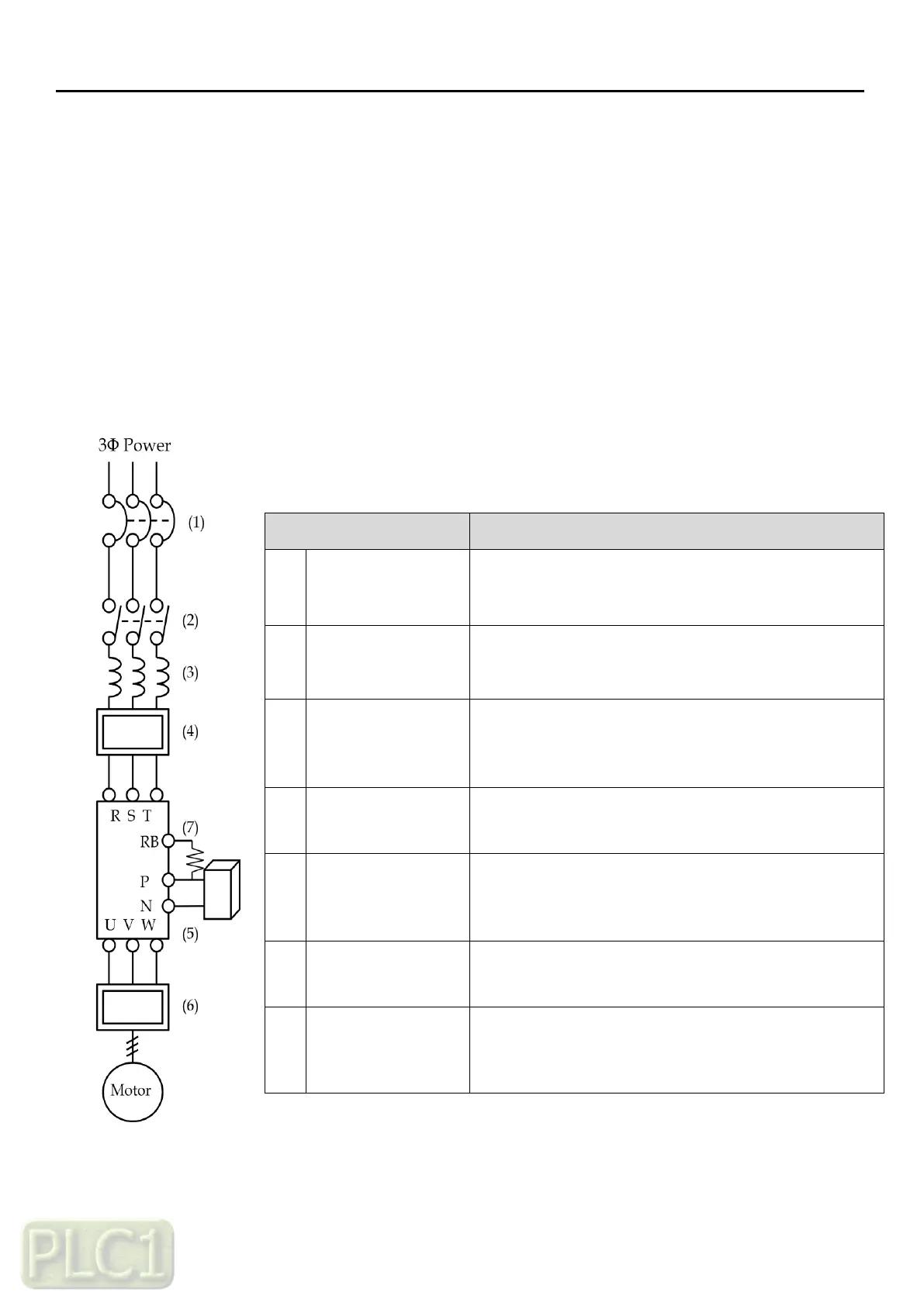
For better system performance enhancement, optional accessories may be used with VFD.
Note1: Be sure to consider the capacity of the circuit breaker to be used.
Note2: Be sure to use larger wire for power lines if the distance exceeds 20m.
Note3: Be sure to use a grounding wire same size of power line or similar.
High current flows in the VFD while power is supplied. Be
careful when you select the switch because the VFD.
This does not have to be necessarily installed, but if you
do, do not start or stop the VFD frequently with the
contactor. It might decrease the life of the VFD.
Recommended to use when the unbalance voltage rate is
3% or more and power supply is 500 kVA or more, and
there is a rapid change in the power supply. It also
reduces harmonics and improves the power factor.
Reduces radiation noise emitted from wire at the input.
Applied 30~132kW(HD)
Used for applications that need to increase the brake
torque of the VFD or to frequently start/stop and to run
high inertia load.
Reduces noise emitted from the VFD motor leads. This
helps to minimize interference with sensitive equipment
(ie: sensors or weight scale).
Applied 5.5~22kW(HD)
Used for applications that need to increase the brake
torque of the VFD or to frequently start/stop and to run
high inertia load.