28
WWW.AEM
-
TEST.COM
customercare@aem-test.com | Version # : 2.2
TestPro CV100
User Manual
m.HybridPower&FiberCerticationTest
A powered ber cable system combines hybrid optical
ber and copper cabling plus electronics to provide a
complete indoor/outdoor solution for both powering and
communicating with HD Cameras, Wi-Fi access points,
small cells, and other PoE devices. It is also known as a
hybridcablesystemasitiscomposedofaberopticcable
which carries the data and two unshielded twisted pair
(UTP) cables attached to a power source.
The powered ber cable system improves speed and
simplies installation, powering, and communication of
network devices -at 30x the distance of traditional CAT
cable systems.
Deployment of HD cameras, Wi-Fi access points, optical
network terminals, small cells, and other network-access
devices can be challenging, especially a PoE input for
power and communications,
but distance limitations, power availability, and device
placement throw a wrench into network planning.
Testing of Powered Fiber Cables
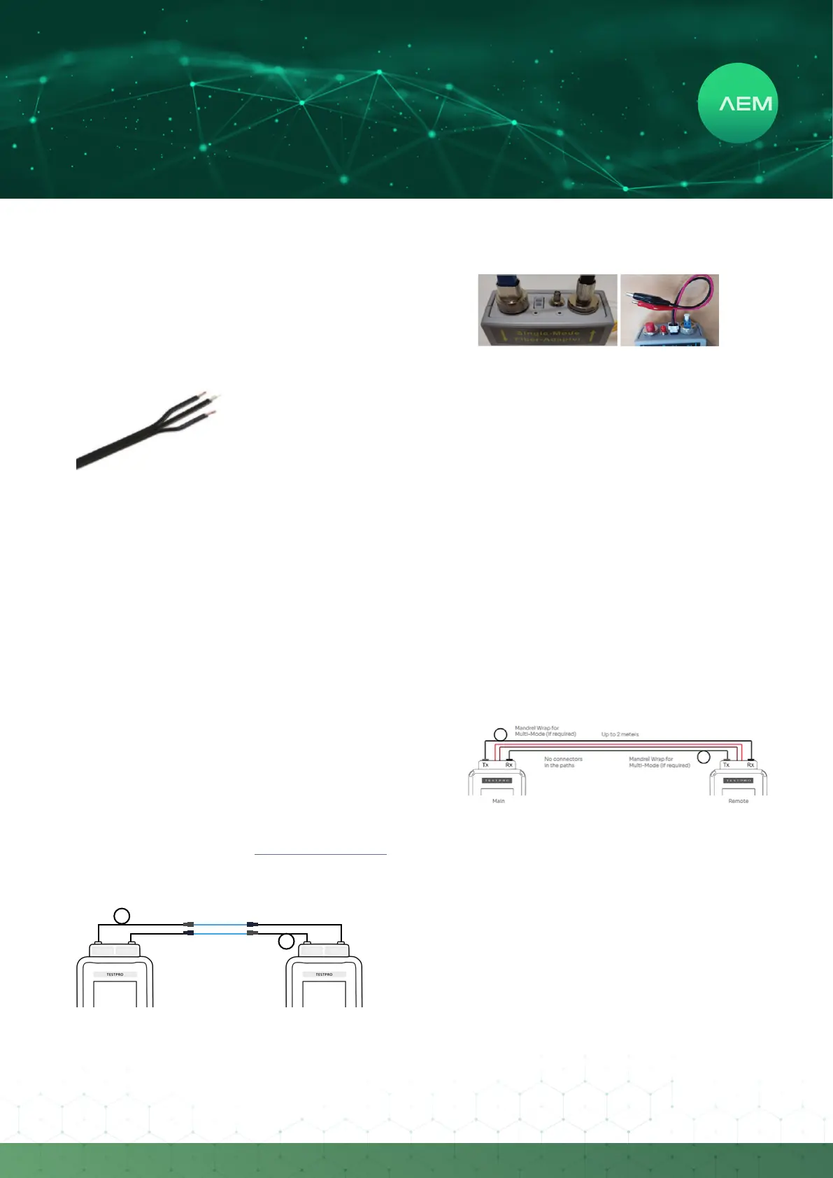
Refer to and follow steps under 3FiberCerticationTest
toperformtheberone-jumpersetreferencefollowedby
steps below.
MandrelWrapfor
Multi-Mode (if required)
MandrelWrapfor
Multi-Mode (if required)
2 meters
Tx Rx
Tx Rx
1. Attachbercables totestbothendsofthereference
cables.
AttachaPoEtestcabletothepowerportoftheber
adapter.
2.
Clip the ‘crocodile clip’ of the POF cable to the open
Ethernet cable pair that carries the voltage i.e. pair 3
and 6. (Note: Ensure that the pairs and the Ethernet
cable are cut open to access these pairs.)
Connect the other end of the cable to a power source
equipment (POE switch, extender or midspan).
PowerontheTestProunitandselect[FiberCertication].
The PSE voltage reading should be displayed below the
FiberMap.
3.
4.
5.
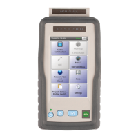
n.FiberPoEDCResistanceTest
Installing a copper cable with less resistance measurement
is the key to powering POE-enabled devices and ensuring
optimum operation and performance. TestPro units,
using a multi-mode or single-mode adapter support the
measurement of copper cable DC resistance in a powered
bercablesystem(alsoknownashybridber,wereber
and copper cables are combined), using the DC connector
thatcomeswiththeberkit.
i:FiberPoEDCSetReference
JustlikeCopperandFiberCerticationtests,itisimportant
to perform set reference to the TestPro main and remote
devices before doing the measurement to get accurate
DC Resistance test results. It is recommended that the
measurement is performed within 10 min of doing “set
reference”.ToperformFiberDCsetreference:
Attachthesinglemodeormultimodeberadapter
to the TestPro main and remote units.
•
Connectingaberinspectionscope:
Power on TestPro, attach SM or MM Fiber adapter and
insert the ber inspection scope into the TestPro unit’s
USB slot, located on the right side of the device. TestPro
willautodetecttheberinspectionscopeandinstallthe
relevant UVC built in drivers.