DD+DIS155
.11E
Functional Description
DOCUMENT CONTROL NOTE:
The controlled version of this document is available from the Agfa HealthCare Library. Any printed copy of this document is uncontrolled.
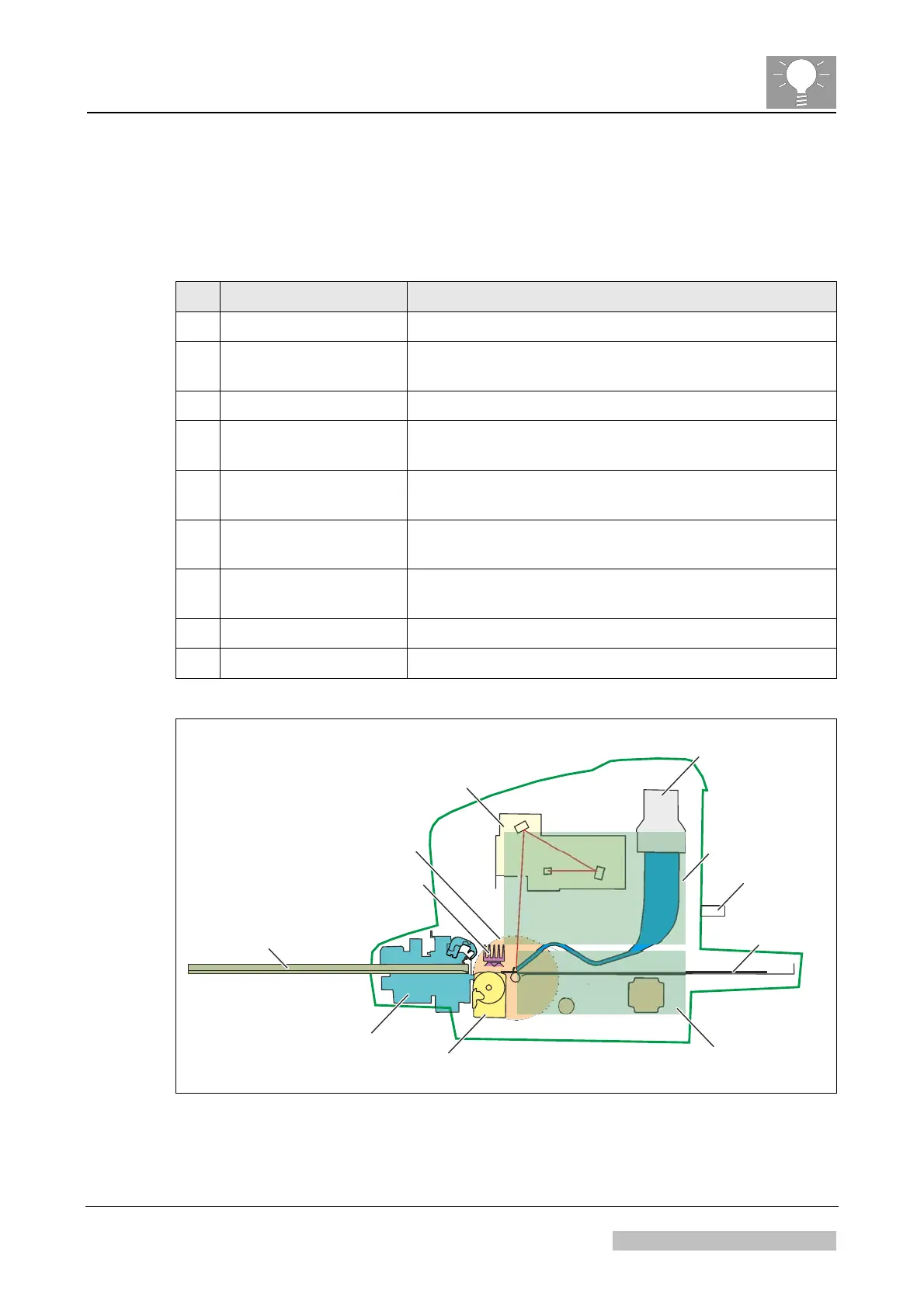
1.4 Main Components of the Digitizer
The digitizer consists of following main components:
# Component Name Purpose
1 Cassette Unit Opens, closes and clamps the cassette.
2 IP-Drawer Module Transports the image plate from cassette to slow scan
drum and back.
3 Erasure Unit Erases the image plate while it is driven back.
4 Slow Scan Unit Drives the image plate continuously during scanning
and erasure.
5 Optic Module Creates the laser beam for scanning This beam
stimulates the image plate to emit blue light.
6 PMT with Light
Collector
Collects the emitted blue light and converts it into an
electrical signal.
7 Power Board Controls the actuators and sensors for the image plate
(IP) run and the erasure unit.
8 PMI Board Main board of the digitizer.
9 USB Flash Memory Keeps the digitizer configuration data and logfiles.
Cassette Unit
IP-Drawer Module
Erasure Unit
Slow Scan Unit
Optic Module
Cassette
PMT with
Light Collector
Power Board
517502ca.cdr
PMI Board
Image Plate
USB Flash
Memory
Figure 4
Edition 1, Revision 1 CR 10-X / CR Reader / CR 12-X / CR Advanced Reader Chapter 2 / Page 6 of 19
03-2013 Type 5151 / 100 / 110 / 200 / 210 Agfa Company Confidential
 Loading...