DD+DIS155
.11E
Functional Description
DOCUMENT CONTROL NOTE:
The controlled version of this document is available from the Agfa HealthCare Library. Any printed copy of this document is uncontrolled.
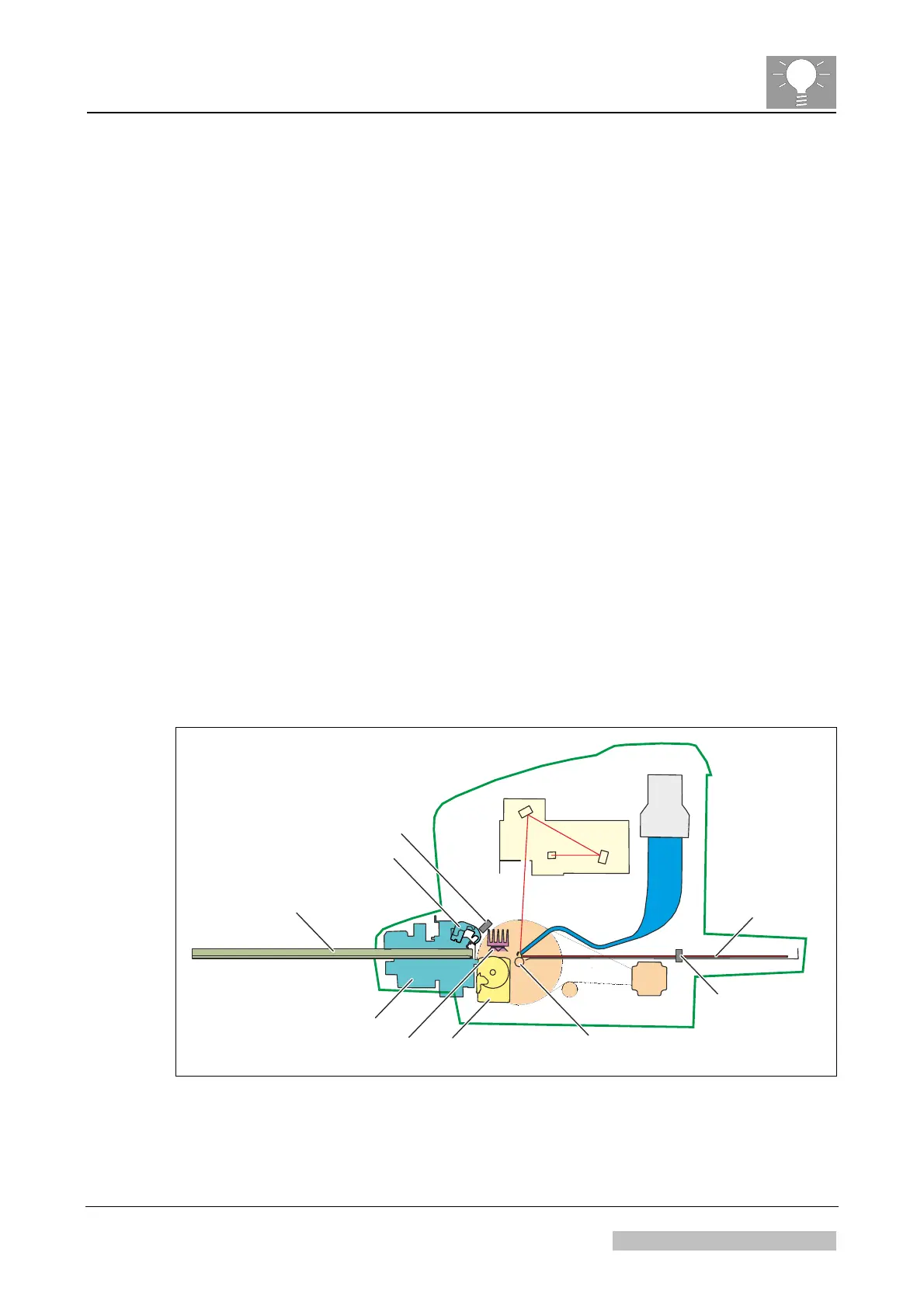
5 Description of the Image Plate Run
This section describes the Image Plate (IP) run of the digitizer for a default scan cycle.
Overview of the main steps:
The user inserts the cassette.
The cassette detection light sensor detects the cassette: The IP drawer pulls
out the image plate towards the drum with four magnets and the magnetic IP
drawer roller.
The laser beam is switched on to read the bar code and the position of the label
on the image plate carrier.
The magnetic slow scan drum drives the image plate during scan. The IP
detection light sensor detects the image plate.
When the slow scan motor has reached the required number of motor steps, it
changes direction: The image plate is transported back.
The erasure unit erases the Image Plate during its movement back into the
cassette.
The last few centimeters of the way back, the IP drawer module drives the
image plate into the cassette.
The green status LED indicates the user to remove the cassette. When taking
out the cassette, it is closed again.
Cassette
Cassette Unit
Cassette Opener
Cassette Detection
Light Sensor
IP Detection
Light Sensor
Slow Scan Drum (Magnetic)
IP-Drawer Module
Erasure Unit
517502fa.cdr
Image Plate in
End Position
Figure 11
Edition 1, Revision 1 CR 10-X / CR Reader / CR 12-X / CR Advanced Reader Chapter 2 / Page 14 of 19
03-2013 Type 5151 / 100 / 110 / 200 / 210 Agfa Company Confidential
 Loading...