5 Select the tachometer parameters.
Press [
Input
] [
TACHOMETR SETUP
].
If the peak-to-peak value exceeds 4 volts, press [
TACH RANG +/- 20 4
] to highlight 20.
Press [
LEVEL
] <number> <unit>. The analyzer detects the tachometer signal at this
level.
Press [
SLOPE POS NEG
] to highlight NEG if you want the analyzer to detect the falling
(negative) edge of the signal.
Press [
TACH PULS PER REV
]<number>[
ENTER
].
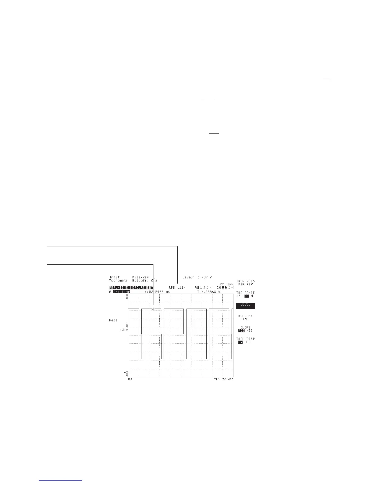
6 Verify tachometer parameters.
Press [
TACH DISP ON OFF
] to highlight ON. The tachometer indicator appears at the
top of the display.
This task uses the Histogram/Time instrument mode. It lets you view the tachometer
input signal in the time domain. Unfiltered time channel data is not processed through
anti-aliasing filters or bandwidth-limiting filters. For more information see online help.
You may be able to use the relative marker to determine the peak-to-peak value of the
signal in Step 5. See “To measure a value relative to a reference” in the first section.
The tachometer indicator displays the number of tachometer transitions. If multiple
transitions occur within any one edge of the signal, you will need to “clean it up” by
specifying a tachometer delay in seconds. See the next task, “To specify tachometer
holdoff time.”
You can use
the markers
to determine
appropriate value for
Tach Display
Agilent 35670A Quick Start Guide Making Measurements
41

 Loading...


