To troubleshoot CPU, memory, and buses failures
Use this test to isolate the failure when the power-on LEDs show a fail code or the
analyzer locks up during the power-up tests.
q
Step 1. Compare the LED fail code to the following table.
•
Set the power switch to off ( O ).
•
Set the power switch to on ( l ) while watching the power-on LEDs.
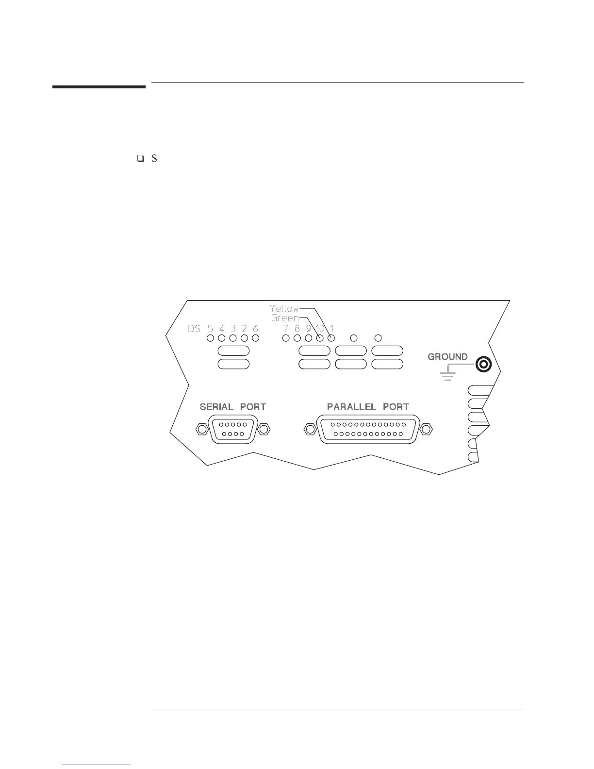
The power-on LEDs are on the A7 CPU assembly and are visible through the rear
panel. To see the LEDs easier, remove the seven screws holding the rear panel to
the analyzer and lean the rear panel back. This also gives you access to reset switch
SW2.
•
Determine the probable faulty assembly by comparing the power-on LEDs
fail code to the following table.
The power-on LEDs are showing a fail code when the LEDs display a code for
more than 4 seconds.
Troubleshooting the Analyzer Agilent 35670A
To troubleshoot CPU, memory, and buses failures
4-18

 Loading...


