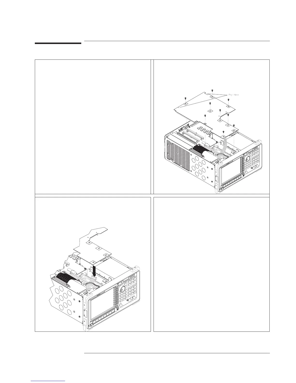
EasyManuals Logo
Home>Agilent Technologies>Measuring Instruments>35670A

Agilent Technologies 35670A Service Guide

Agilent Technologies 35670A
439 pages
To Next Page IconTo Next Page
To Previous Page IconTo Previous Page
Page #281 background imageLoading...
Page #281 background image
To remove CPU
1 Remove cover (see ‘’To remove cover’’). 2 Using a T-10 torx driver, remove the nine
screws from the A7 CPU assembly. Lift the
assembly up, unpluging the A7 CPU assembly from
the A8 Memory assembly and A99 Motherboard.
3 Disconnect the ribbon cables from the A7
CPU assembly.
4 The analyzer’s serial number and firmware
options are stored in EEPROM (U27) on the A7
CPU assembly. Before replacing the CPU
assembly, remove A7 U27 from the faulty assembly
and insert into the new assembly. See ‘’What to do
before replacing the CPU assembly’’ on page 6-3.
Agilent 35670A Replacing Assemblies
To remove CPU
6-11

Table of Contents

Other manuals for Agilent Technologies 35670A

Questions and Answers:

Question and Answer IconNeed help?

Do you have a question about the Agilent Technologies 35670A and is the answer not in the manual?

Agilent Technologies 35670A Specifications

General IconGeneral
BrandAgilent Technologies
Model35670A
CategoryMeasuring Instruments
LanguageEnglish

Related product manuals