A99 Motherboard
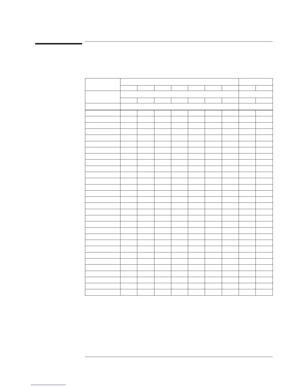
The following table lists all signals routed through the Motherboard. The table uses
bold face type to show which assembly can generate the signal. A description of each
signal follows the ‘’Motherboard Voltages’’ table.
Signal Name
Assembly Using Signal
A1/A2 A2 A5 A6 A7 A10 A90 A98 Ext Mon
Motherboard Connector
J1 J2 J5 J6 J7 P10 P90 P98 P95
Connector Pin Number
A10MHZ 150
59
ADCOLn 17B
17A
ADCULn 17C
17B
ADDATA 20C
20A
B5MHZ 148
60
BRESETn
12A 12B
112
BTACH
32A
10
CALP
C1 C1
1A
CEHPIBn 138
25
CEONIXn 139
31
CHSYNCn
18C
18A
DACCLK
9C
9B
DACDAT
10C
10A
DACUPDn
8C
8B
DITHER 11A
11A
DSPTRIG 25A
125
DSR 46
11
ECLK
22C
72
EFFSMP
19C
18B
EXTRGIN
32B
8
FA1
13B
64
FA2
13C
114
FA3
14B
65
FA4
14C
115
FA5
15B
66
FAN+ 43
2
FANFUL 93
46
FANOFF 143
45
FANTRIP 9A
61
FD0 25B 76
Agilent 35670A Voltages and Signals
A99 Motherboard
9-25
 Loading...


