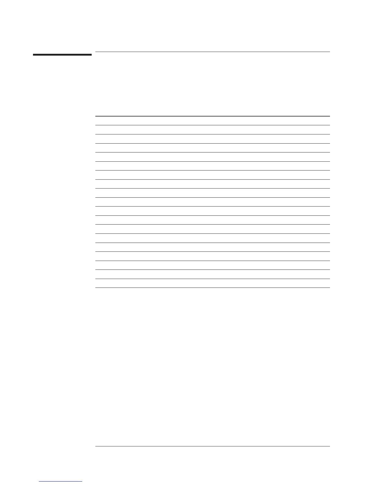
A100 Disk Drive
The following table lists signals routed between the A100 Disk Drive assembly and
the A7 CPU assembly. This table shows several things — if the assembly generates or
uses the signal or voltage, and if a signal is bidirectional. A description of each signal
follows the table.
Signal Name
Pin(s) A7 P3 A100
DIR
17 S •
DISKINn
22 • S
DRIVESELn
21, 29 S •
DSKCHGn
1•S
HDSEL
3S•
HIDENSn
33 • S
INDEXn
27 • S
MTRn
19, 31 S •
ReDATAn
5•S
SEL0
25 S •
SEL1
23 S •
STEPn
15 S •
T00n
9•S
WDATA
13 S •
WGATE
11 S •
WRIPROTn
7•S
+5 V
24, 26, 28 • •
Gnd
2-20 (even) • •
Not Used
30, 32, 34 — —
S This assembly is the source of the signal.
• This assembly uses the signal.
— This assembly does not use this signal.
Voltages and Signals Agilent 35670A
A100 Disk Drive
9-34

 Loading...


