A9 NVRAM
The optional A9 NVRAM assembly provides the A7 CPU assembly with additional
nonvolatile RAM.
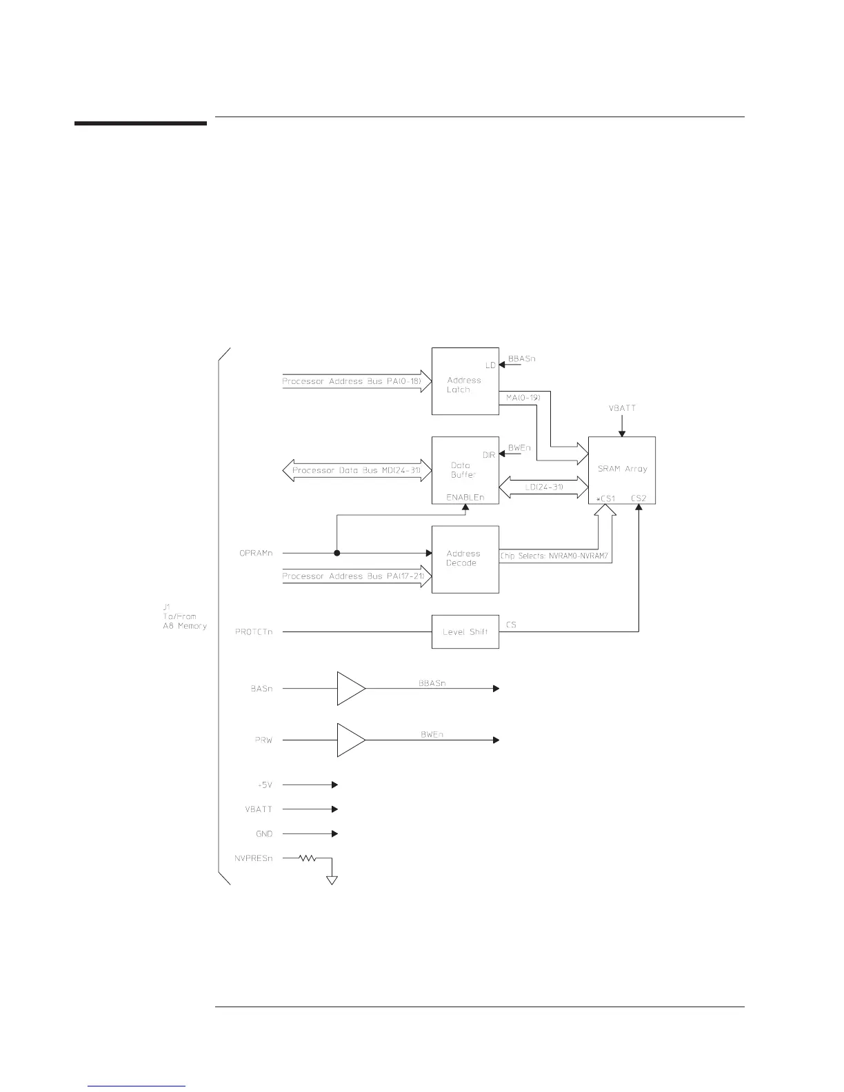
Address Latch Holds the address from the processor address bus. This circuit latches the address when an
address strobe occurs (BBASn goes low).
Data Buffer Buffers the processor data bus.
Address Decode Enables one of the eight battery-backed static RAM chips in the SRAM Array.
Level Shift Disables the SRAM Array during power-up and power down, when the A7 CPU assembly’s
processor is externally reset, and when +5 volts on the A8 Memory assembly is too low.
SRAM Array Contains eight battery-backed static RAM chips.
A9 NVRAM Block Diagram
Circuit Descriptions Agilent 35670A
A9 NVRAM
8-32

 Loading...


