•
If the signal does not toggle after SW2 is pressed, the A7 CPU assembly is
probably faulty.
•
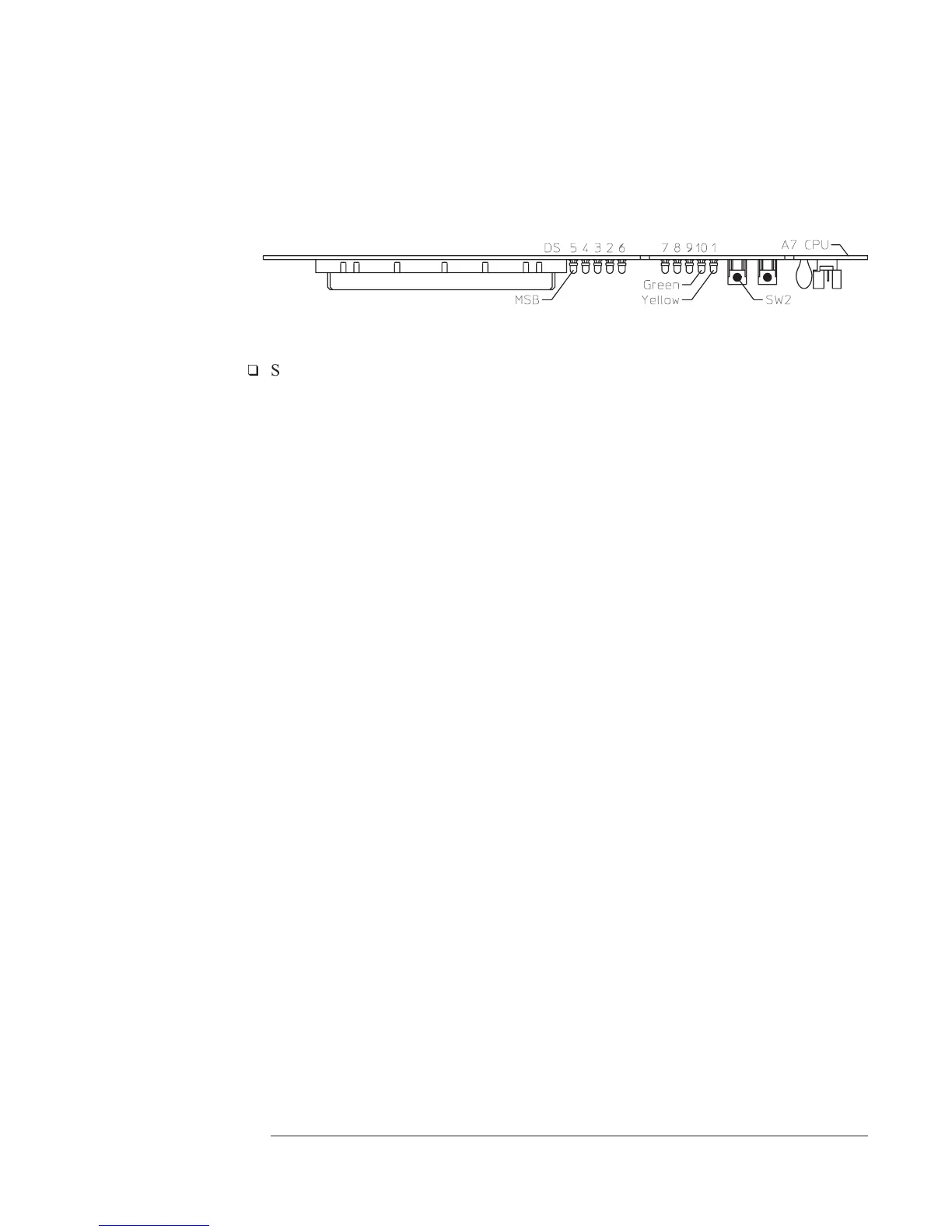
If no error messages are displayed after Booting System or A7 DS101 (green
run LED) is off, go to page 4-29, ‘’To troubleshoot fast bus failures.’’
q
Step 3. Check the serial data line (SDA).
•
Attach the logic probe to A7 P7 pin 1 (SDA).
•
Press SW2 while monitoring A7 P7 pin 1 (SDA), the power-on LEDs, and
the display.
The TTL logic level should toggle when 00 is displayed and toggle continuously
when
Booting System is displayed. The following failure message should be
displayed after
Booting System and the display grid should appear about 2 minutes
after power up.
Front Panel failure information:
keyboard IIC chip fails:
IIC: No Device Acknowledge
key stuck: 32
A power-on test has failed. Refer
servicing to qualified personnel.
Press Start key to attempt to continue
power-up.
•
If the signal does not toggle after SW2 is pressed or the failure message is
not displayed, the A7 CPU assembly is probably faulty.
Agilent 35670A Troubleshooting the Analyzer
To troubleshoot IIC bus failures
4-27

 Loading...


