q
Step 2. Check the tachometer range function.
•
Set the oscilloscope for 20 s/div.
•
Press the following keys:
[
Rtn ]
[
LOOP MODE OFF ]
[
Rtn ]
[
SERVICE TESTS ]
[
SPCL TEST MODES ]
[
SOURCE LEVEL ]
[
Source ]
[
SOURCE ON ]
[
LEVEL ]
500
[ mVpk ]
[
Trigger ]
[
TACHOMETR SETUP ]
[
TRG RANGE +/− 20 ]
•
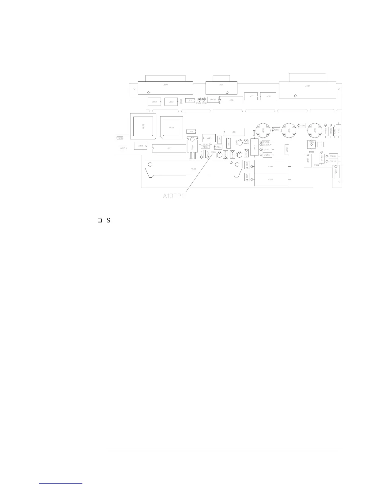
Check that the oscilloscope displays a dc voltage of approximately 4 Vdc.
•
Press [ TRG RANGE +/ 4].
•
Check that the oscilloscope displays a 4 0.4 Vp-p, 10.24 kHz sine wave,
with 2 ±0.2 Vdc offset.
•
If the signal is incorrect, the A10 Rear Panel assembly is probably faulty.
•
If the signal is correct, the A6 Digital assembly is probably faulty.
Agilent 35670A Troubleshooting the Analyzer
To troubleshoot tachometer failures
4-71

 Loading...


