EasyManuals Logo

Agilent Technologies 35670A Service Guide

Agilent Technologies 35670A
439 pages
To Next Page IconTo Next Page
To Previous Page IconTo Previous Page
Page #329 background imageLoading...
Page #329 background image
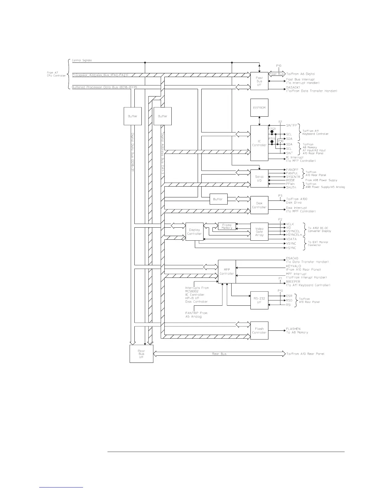
A7 CPU Block Diagram: Interface
Reset Logic Puts the analyzer into a known state. A reset occurs at power-up and power-down (PVALID
from the A98 Power Supply assembly goes high), when the reset switch S2 (located on the
CPU assembly) is pressed, or when a RESET instruction is executed.
Agilent 35670A Circuit Descriptions
A7 CPU
8-27

Table of Contents

Other manuals for Agilent Technologies 35670A

Questions and Answers:

Question and Answer IconNeed help?

Do you have a question about the Agilent Technologies 35670A and is the answer not in the manual?

Agilent Technologies 35670A Specifications

General IconGeneral
BrandAgilent Technologies
Model35670A
CategoryMeasuring Instruments
LanguageEnglish

Related product manuals