Agilent 5577B/BL/C/D/DL/FL User’s Guide xi
Figures
Figures
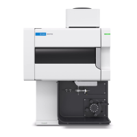
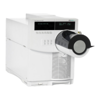
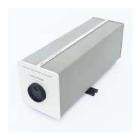
Figure 1. Agilent 5517B/C/D and 5517BL/DL/FL Laser Heads 3
Figure 2. Agilent 10881A/B/C Laser Head Cable. 19
Figure 3. Agilent N1251B High Performance Laser Head Cable 20
Figure 4. Agilent 10881D/E/F Laser Head Cable 21
Figure 5. Agilent 10791A/B/C Laser Head Cable 22
Figure 6. Installation of laser system cables 23
Figure 7. A1 Connector board, component side, showing fuse locations and high voltage
connectors 26
Figure 8. A3 Controller/Reference Board 27
Figure 9. Laser position transducer mounting 29
Figure 10. Front Panel Turret and Aperture 33
Figure 11. Measuring the laser beam power with power meter detector 34
Figure 12. Split frequency test setup 35
Figure 13. Jumper Locations on A3 Controller/Reference Board (05517-60031) 47
Figure 14. Jumper Locations on A3 Controller/Reference Board (05517-60003) 47
Figure 15. High voltage area and anode lead 48
Figure 16. Three-pin high voltage power supply connector 48
Figure 17. Typical single-axis Agilent Laser Interferometer Positioning System 53
Figure 18. Start/Programs pop-up menu 57
Figure 19. Monitor screen after opening the application 58
Figure 20. Measurement screen 59
Figure 21. Laser Head—primary troubleshooting flowchart 65
Figure 22. Board trouble isolation flowchart 66
Figure 23. DS1 through DS4 locations on A3 Controller/Reference Board 67
Figure 24. DS4, DS6, Q3, TP1 and TP8 locations on A3 Controller/Reference Board 67
Figure 25. Laser head cover removal 69
Figure 26. Agilent 5517B/C/D Laser Head dimensions and mounting location 78
Figure 27. Agilent 5517BL/DL/FL Laser Head dimensions and mounting location 79
 Loading...

