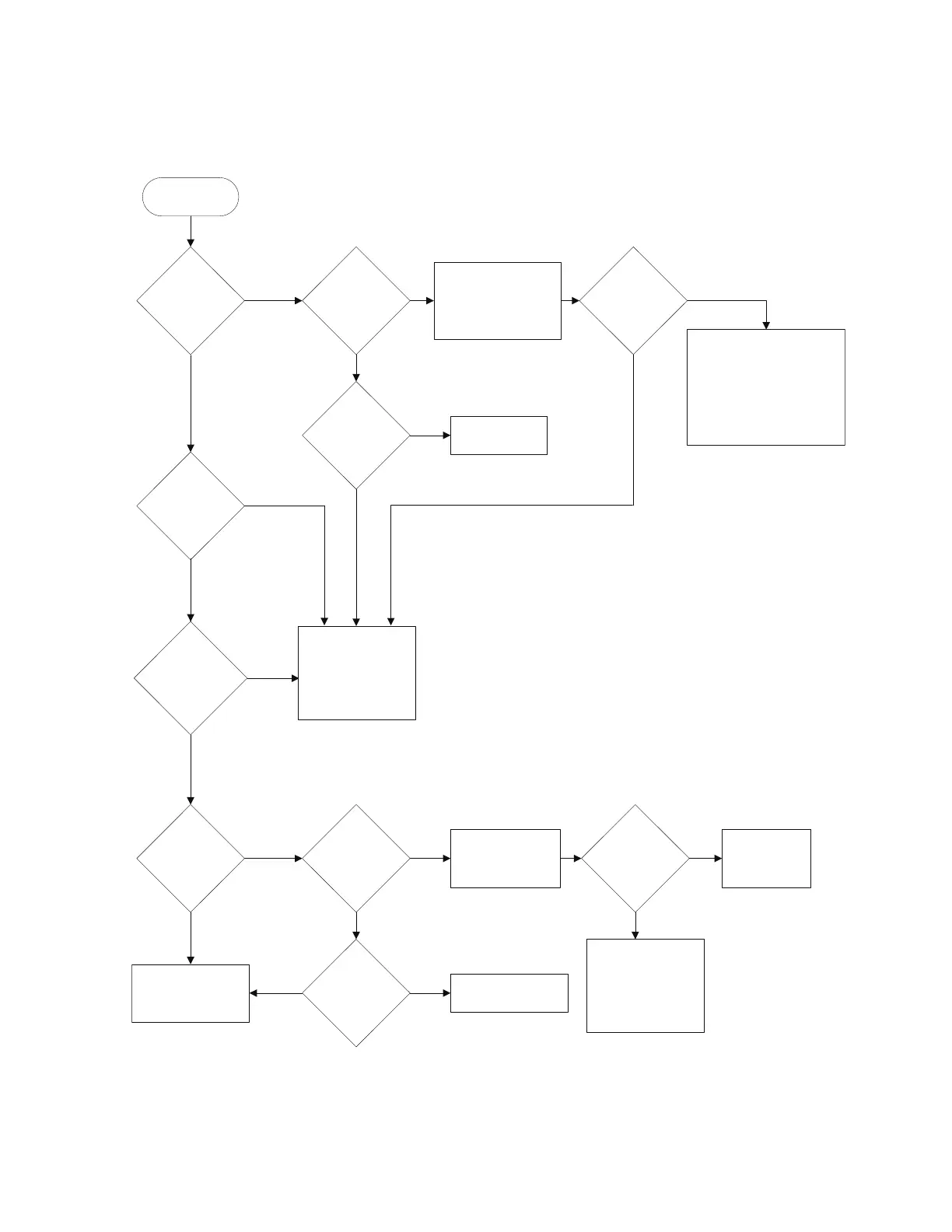
START
Is red
laser beam
visible (either
continous or
flashing?
Is
laser beam
flashing?
YES
Is
LASER ON
LED lit?
Is
front turret
in the correct
posiition?
YES
YES
NO
±0.3V
(See note )
NO
NO
Reposition
turret
Voltages OK?
Problem is not in the laser
head.
Check the following:
1. Laser head cable
2. Laser head power supply
(10884 or other)
3. Measurement electronics
power supply (5507 only)
NO
YES
YES
Is laser
power output
low?
NO
YES
YES
YES
NO
NO
Check Ref/laser
head cable
continuity.
NO
Is it OK?
Replace Ref/
laser
head cable.
Note
LASER ON LED.
The 15V specifications apply when the cable is loaded with the
nominal operating current.
This adjustment assumes that all the receivers are also
connected.
Replace laser tube and
high voltage power
supply.
NO
YES
Is Split Freq
within range?
System problem exists
elsewhere.
YESNO
Indicates a problem
with the internal circuitry
of the laser head.
See the board trouble
isolation flowchart on the
next page.
Indicates a problem
with the internal circuitry
of the laser head.
See the board trouble
isolation flowchart on the
next page.
After warmup
the laser head
READY LED
remains on
Check input power
at the laser head
cable connector.
Pins G, H, S = GND
Pins K, M, T = +15V
-15V ±0.3V (although it does not affect
Also check pin L for
Is Ref Signal
present at
measurement
electronics?

 Loading...


