26 Agilent 5517B/BL/C/D/DL/FL User’s Guide
3 Installation
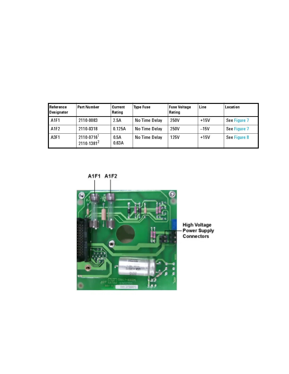
The laser head has three internal fuses: two that protect the ±15V lines of
the laser head, both of which are located on the A1 connector board (see
Figure 7), and one fuse that protects the +15V line to the digital and
analog circuitry located on the A3 Controller/Reference Board (see
Figure 8). All three fuses are accessible by removing the cover of the laser
head (see “Disassembly Procedures" on page 68). Table 8 lists the fuse
values.
1
For A3 Controller/Reference Board p/n 05517-60003.
2
For A3 Controller /Reference Board p/n 05517-60031and 05517-60032.
Figure 7 A1 Connector board, component side, showing fuse locations and high voltage
connectors
Tab le 8 Laser head internal fuses
Reference
Designator
Part Number Current
Rating
Type Fuse Fuse Volta ge
Rating
Line Location
A1F1 2110-0083 2.5A No Time Delay 250V +15V See Figure7
A1F2 2110-0318 0.125A No Time Delay 250V –15V See Figure7
A3F1 2110-0716
1
2110-1381
2
0.5A
0.63A
No Time Delay 125V +15V See Figure8

 Loading...


