68 Agilent 5517B/BL/C/D/DL/FL User’s Guide
7 Service
Disassembly Procedures
Tools Required
• Hand TORX® #8 (T8), #10 (T10), and #15 (T15) screwdrivers
• Flat- blade screwdriver
• Posidrive screwdriver
The following procedures are disassembly procedures and apply to all laser
heads. Reverse the procedures to install the assemblies.
Refer to the exploded view illustration in Figure 26 on page 87 for help in
identifying the assemblies.
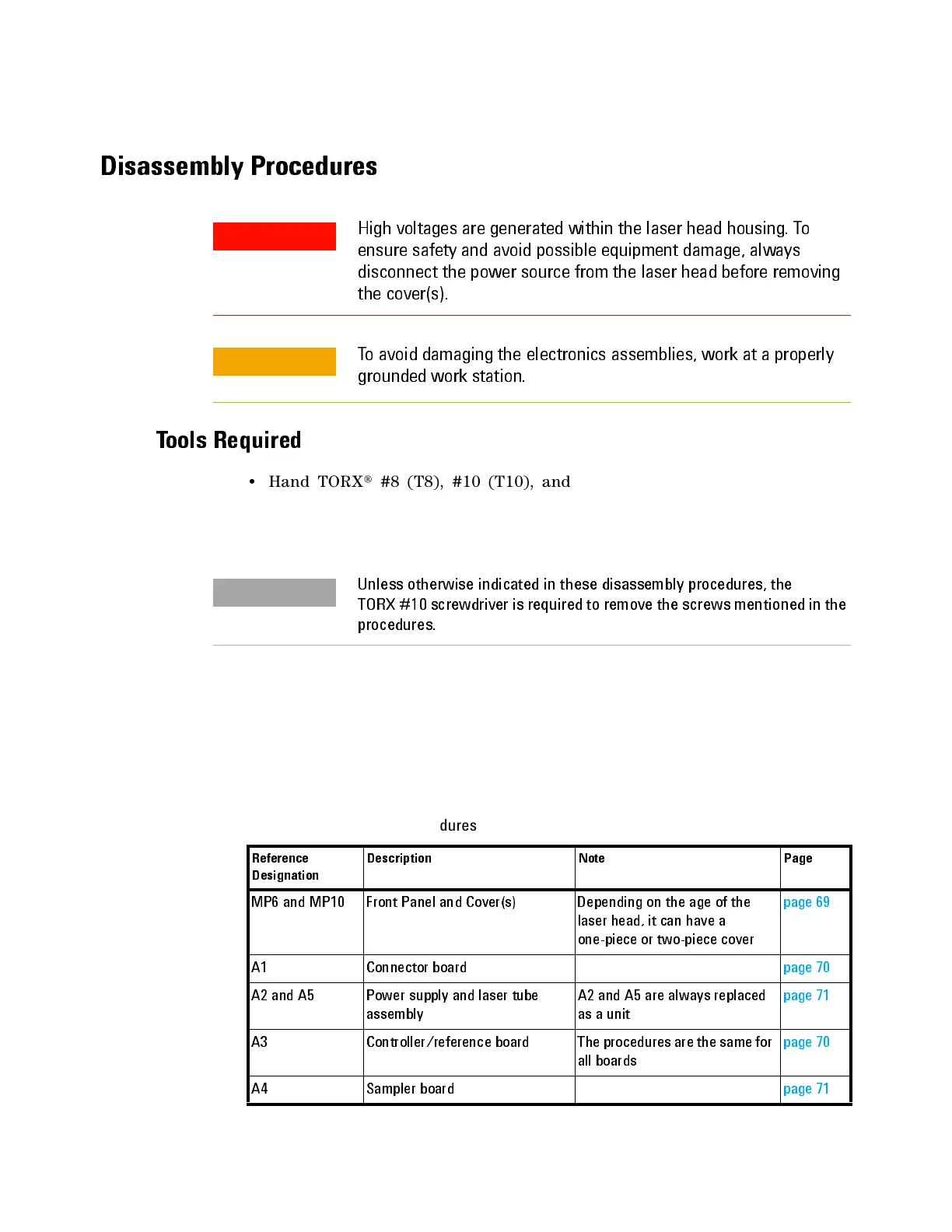
Table 14 lists the disassembly procedures.
High voltages are generated within the laser head housing. To
ensure safety and avoid possible equipment damage, always
disconnect the power source from the laser head before removing
the cover(s).
To avoid damaging the electronics asse mblies, work at a properly
grounded work station.
Unless otherwise indicated in these disassembly procedures, the
TORX #10 screwdriver is required to remove the screws mentioned in the
procedures.
Tab le 1 4 Disassemble procedures
Reference
Designation
Description Note Page
MP6 and MP10 F ron t Pa ne l an d Cov er (s) D epe n din g on the age of th e
lase r he ad, it ca n h av e a
one-piece or two-piece cover
page69
A1 Connector board page70
A2 and A5 Power supply and laser tube
assembly
A2 and A5 are always replaced
as a unit
page71
A3 Controller/reference board The procedures are the same for
all boar ds
page70
A4 Sam pler boar d page71

 Loading...


