64 Agilent 5517B/BL/C/D/DL/FL User’s Guide
7 Service
Laser Head Troubleshooting
Exchange 5517DL Laser Tube Assemblies
The laser tube within the Agilent 5517DL Laser Head is available as a
replacebale part. Table 13 lists laser tube assemblies within the
Agilent 5517DL Laser Head that can be replaced on an exchange basis.
Factory repaired and tested exchange tube assemblies are available only
on a trade- in basis. Defective assemblies must be returned for credit..
Troub leshooting
The following symptoms indicate problems with Agilent Laser Head Laser
Head:
• No laser light is being emitted from the laser head exit port.
• Low power output from the laser head.
•
LASER ON
indicator not lit.
•
READY
indicator does not illuminate as expected. Normally, the indicator
will start to blink on and off within four minutes of applying power to
the laser head. This indicates that the laser head is in the process of
warming up. When the laser head is ready for use, the indicator
assumes a steady on condition.
• Absence of reference signal or bad reference signal.
• The
+15V POW E R ON
or
–15V POWER ON
indicator on the laser head is not
lit.
If one or more of the above symptoms are observed, use the
troubleshooting flowchart, Figure 21, to assist in determining if the laser
head is actually at fault.
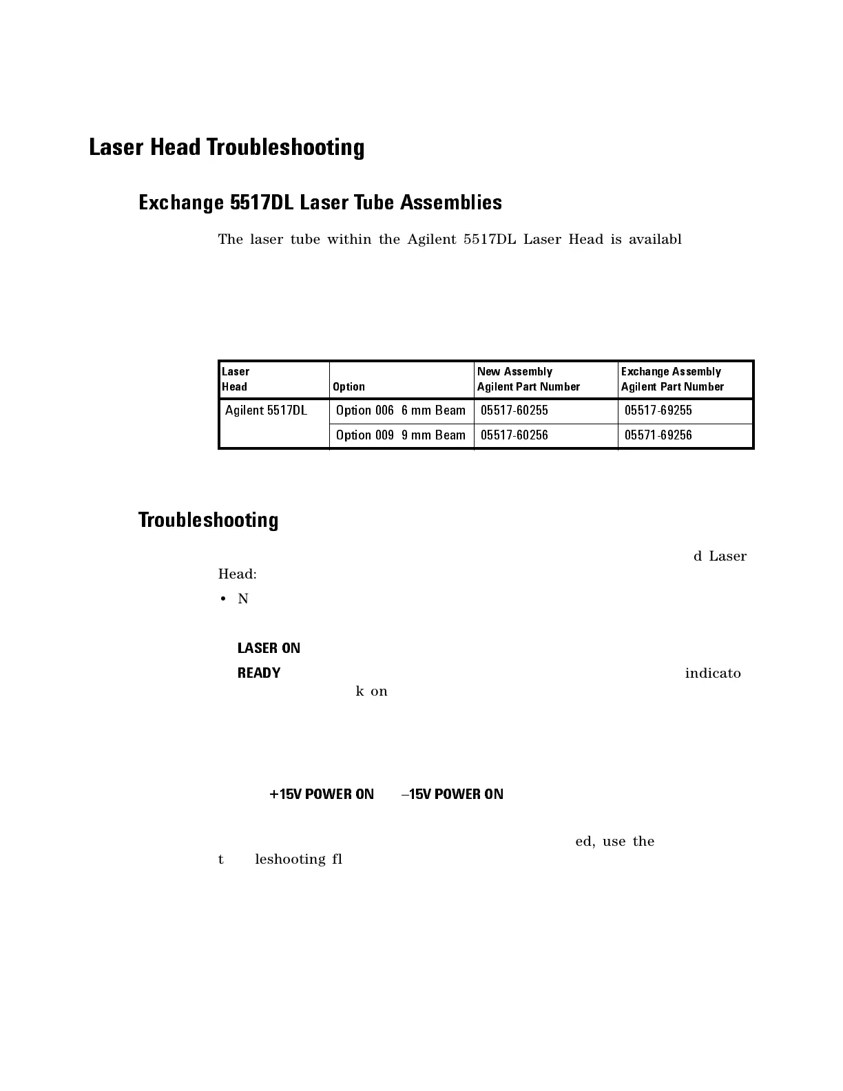
Tab le 1 3 Exchange Laser Tube Assemblies
Laser
Head
Option
New Assembly
Agilent Part Number
Exchange Assembly
Agilent Part Number
Agilent 5517DL Option 006 6 mm Beam 05517-60255 05517-69255
Option 009 9 mm Bea m 0551 7-60 256 05571 -692 56

 Loading...


