Installation 3
Agilent 5517B/BL/C/D/DL/FL User’s Guide 21
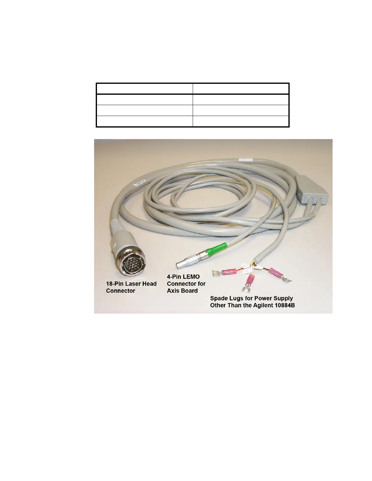
Figure 4 Agilent 10881D/E/F Laser Head Cable
Figure 6 on page 23 shows typical connections to the laser head, axis
board and the 10881A/B/C or 10791A/B/C laser head cables. Not shown
are the spade lugs of the 10881D/E/F laser head cables used with a power
supply other than the 10884B.
The figure also shows a typical connection of a receiver to an axis board.
There are a variety of receivers and receiver cables to choose from. For
more information on the receivers, cables and axis boards, see the Laser
and Optics User's Manual or the individual receiver and axis board
manuals.
Tab le 5 Terminal connections (three spade lugs)
Wire Color Voltage
Red +15 V
Black –15 V
Yellow Common

 Loading...


