Installation 3
Agilent 5517B/BL/C/D/DL/FL User’s Guide 29
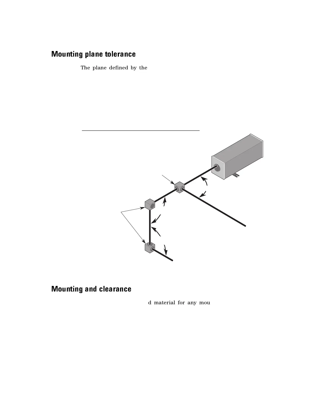
Mounting plane tolerance
The plane defined by the three mounting feet on the laser head must be
parallel to either the bottom or the sides of the beam-splitters and to the
beam-bender housings to within ±3°. It must also be parallel to the bottom
or sides of the interferometers to within ±1°. This ensures the polarization
axes of the interferometers are oriented properly relative to the
polarization vectors of the laser beam (See Figure 9). The laser head can
be rotated in 90° increments about the beam axis (roll) without affecting
the system performance, but the measurement direction sense will change
with each 90° rotation.
Figure 9 Laser position transducer mounting
Mo un tin g an d cle ar a nc e
Aluminum is the preferred material for any mounting surface, since this
will match the thermal coefficient of expansion of the laser base. If
aluminum cannot be used, kinematic mounting of the rear mounting foot is
recommended to minimize stresses due to temperature changes.
Mount the laser head using the three slotted mounting feet that extend
outward from the bottom edges of the unit (depending on the laser head
model you are using, refer to Figure 26 on page 78 or Figure 27 on
page 79 for exact locations and dimensions). The mounting feet may be
90
°
±
3
°
90
°
±
3
°
90°
±
3°
LASER POSITION TRANSDUCER MOUNTING
Beam Splitter
Beam Bender

 Loading...


