Installation 3
Agilent 5517B/BL/C/D/DL/FL User’s Guide 23
This 4- pin BNC is also keyed to fit together only one way. Match the
internal male and female parts of one connector with their
counter- parts in the other connector. Push the cable connector in and
secure it by turning the locking ring so it engages with the tabs on the
axis board connector.
3 Connect the three spade lugs to the terminals of a power supply other
than the 10884B as shown in Table 5 on page 21.
4 Connect the power supply to ac line and turn it on.
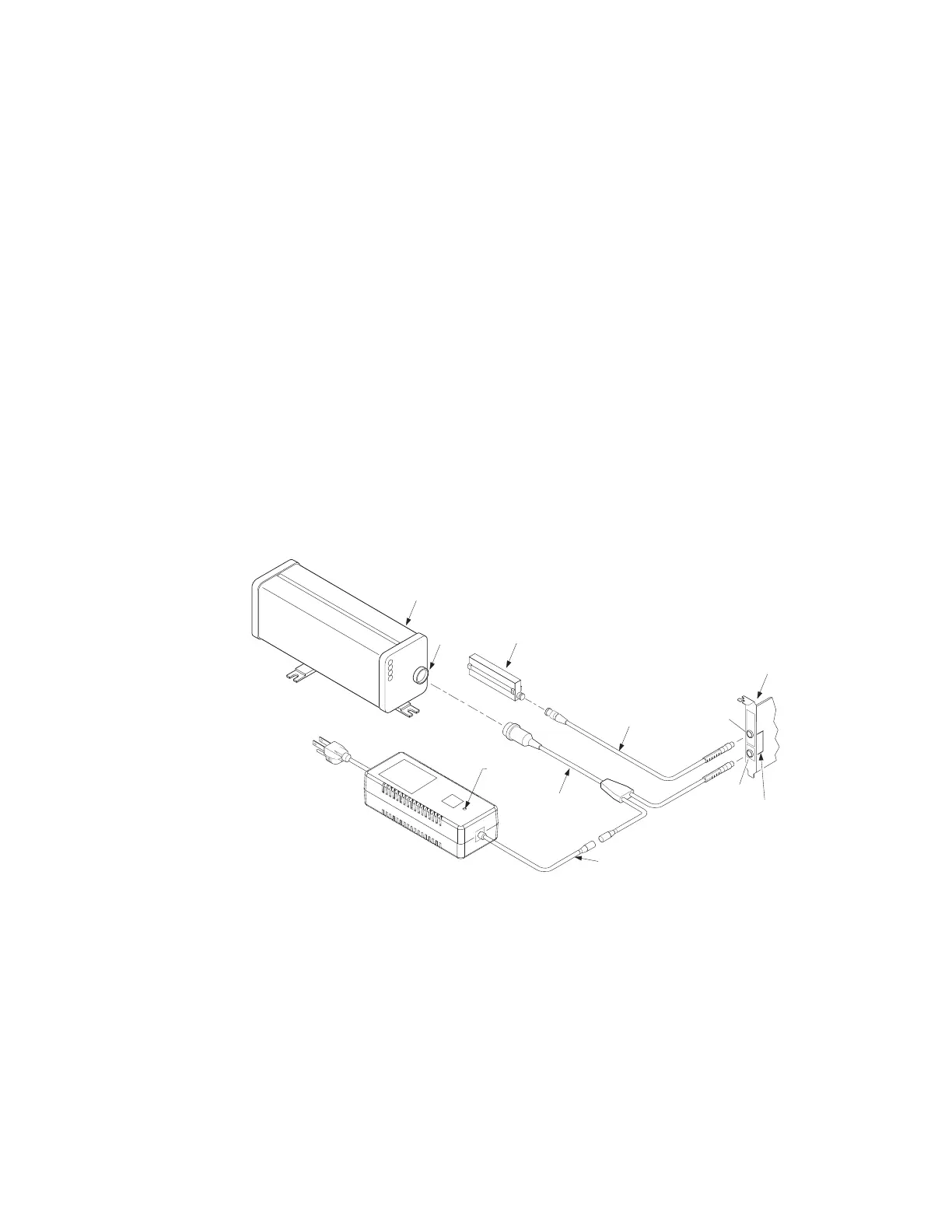
Figure 6 shows typical connections to the laser head, axis board and
the 10881A/B/C or 10791A/B/C laser head cables. Not shown are the
spade lugs of the 10881D/E/F laser head cables used with a power
supply other than the 10884B.
The figure also shows a typical connection of a receiver to an axis
board. There are a variety of receivers and receiver cables to choose
from. For more information on the receivers, cables and axis boards,
see the Laser and Optics User's Manual or the individual receiver and
axis board manuals.
Figure 6 Installation of laser system cables
Table 6 lists all of the power and signal lines available at the rear panel
connector of the laser head.
Agilent 10884B
Power Supply
Axis Board
Receiver
Receiver Cable
Laser Head
Cable
Laser Head
Rear Panel
Connector
AC Line
Input
110-240 Vac
50-60 Hz
Reference
Measure
Cable
(Part of Agilent 10884B)
Trace on Board
for +15V
Power on
Indicator

 Loading...


