Installation 3
Agilent 5517B/BL/C/D/DL/FL User’s Guide 27
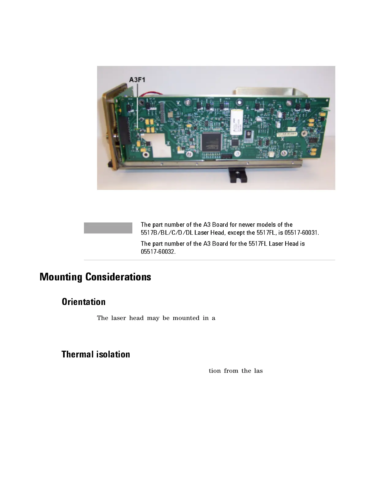
Figure 8 A3 Controller/Reference Board
Mounting Considerations
Orientation
The laser head may be mounted in any orientation as long as it is
positioned so the beam is directed into the optical system parallel to, or
orthogonal with, the machine axes being measured.
Th ermal is o l at i o n
Because there is some heat dissipation from the laser heads, you should
choose the mounting method and location with care. Where possible,
mount the laser head away from the measuring area, to avoid any thermal
effects.
The part number of the A3 Board for newer models of the
5517B/BL/C/D/DL Laser Head, except the 5517FL, is 05517-60031.
The part number of the A3 Board for the 5517FL Laser Head is
05517-60032.

 Loading...


