Using the Laser Head in a System 6
Agilent 5517B/BL/C/D/DL/FL User’s Guide 53
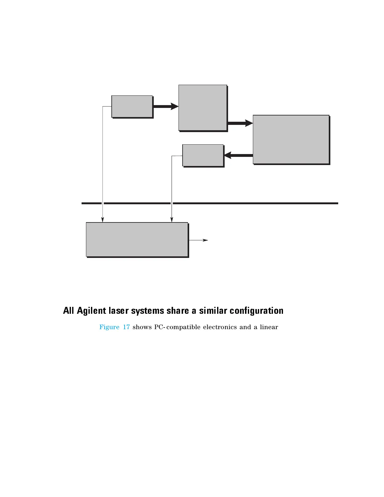
Figure 17 Typical single-axis Agilent Laser Interferometer Positioning System
All Agilent laser systems share a similar configuration
Figure 17 shows PC- compatible electronics and a linear interferometer, but
the system configuration is the same for all types of Agilent electronics
and interferometers.
All Agilent laser systems require a reference signal from the laser head
and a measurement signal from the receiver to be connected to the
electronics to determine relative movement between the optics.
All Agilent laser systems feature separate laser head, interferometer, and
reflector. The laser beam must be aligned with the optical elements and
the motion of the optics to preserve beam alignment and provide an
accurate measurement. The optics and receiver must be aligned so the
beam strikes the lens of the receiver to generate a measurement signal.
Misalignment results in loss of the measurement signal.
Laser Head and Optics
Measurement System Electronics
Laser
Beam
Reference
Frequency
Measurement
Frequency
Laser
Beam
Laser
Beam
(Described in this Manual)
(Described in other Manuals)
Measurement Data
Beam-directing
Optics
Laser Head
Receiver
Measurement System Electronics
Personal Computer (PC)
Agilent N1231B PCI Board
Agilent 5517C
(beam benders,
beam splitters)
Measurement
Optics
Agilent 10702A Interferometer
and
Agilent 10703A Retroreflector
Agilent E1708A

 Loading...


