Performance Tests 4
Agilent 5517B/BL/C/D/DL/FL User’s Guide 35
Split frequency test
Equipment needed
• Power supplies
• Laser head cable
• Laser Breakout Box
• BNC cable
• Frequency counter
Procedure
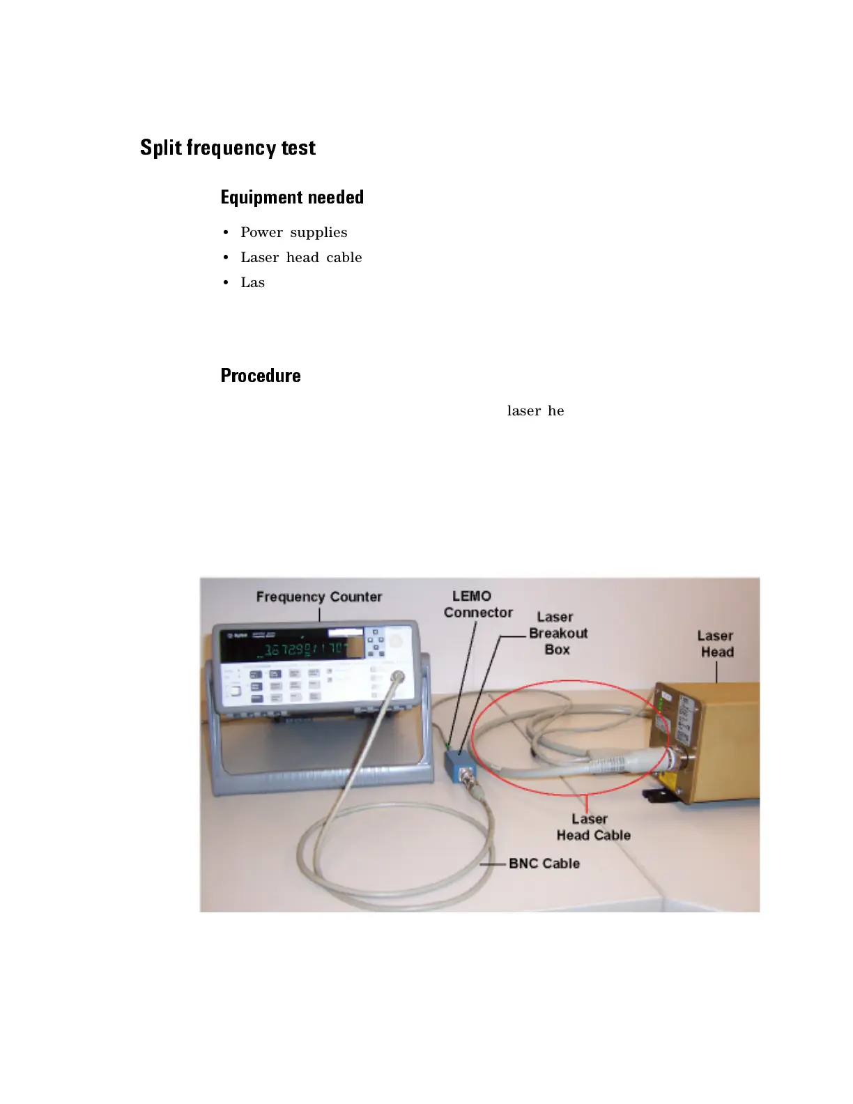
1 Connect the laser head cable to the laser head, using the 18- pin
connector end of the cable shown in Figure12.
2 Connect the power- connector end of the laser head cable to the power
supply.
3 Connect the laser head LEMO connector to the Laser Breakout Box as
shown in Figure12, and connect the BNC connector from the Laser
Breakout Box to the BNC cable to Channel 1 on the frequency counter.
Figure 12 Split frequency test setup

 Loading...


