22 Agilent 5517B/BL/C/D/DL/FL User’s Guide
3 Installation
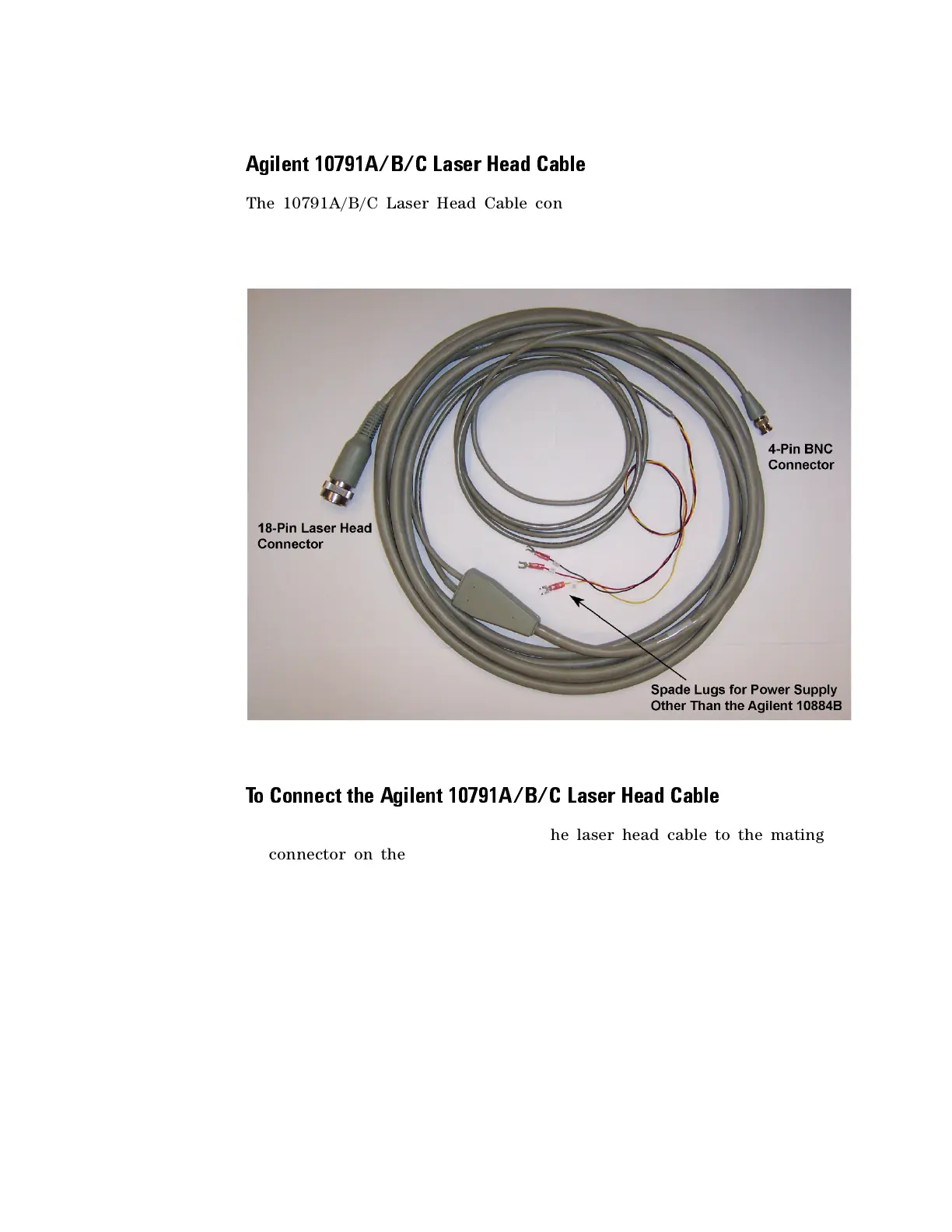
Agilent 10791A/B/C Laser Head Cable
The 10791A/B/C Laser Head Cable connects any of the laser heads
described in this manual to the Agilent 10895A VME axis board. The
cables are Y- shaped and have three connectors, all different, as shown in
Figure 5.
Figure 5 Agilent 10791A/B/C Laser Head Cable
To Connect the Agilent 10791A/B/C Laser Head Cable
1 Connect the largest connector on the laser head cable to the mating
connector on the rear panel of the laser head.
This 18- pin laser head connector is keyed to fit together only one way.
The Agilent logo will be on the top of the connector boot when the
connection is correctly made. The cable connector has locking rings,
which require a clockwise
1
/
3
- turn to secure the cable to the mating
connector. See Table 6 on page 24 for pin- outs of this connector.
2 Plug the smallest connector on the laser head cable into the Reference
connector on the axis board.

 Loading...


