Routine Maintenance: General
Maintaining a sampling valve (rotary type)
Released: March 2004 6850 Series II GC User Information page 112 of 256
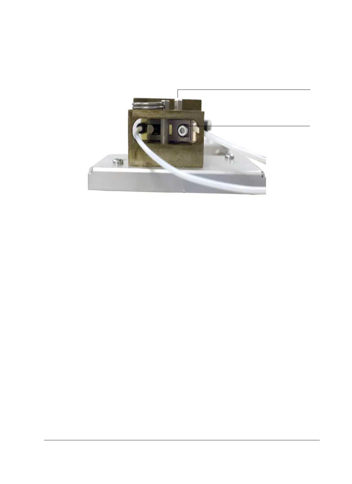
4. Loosen the adjustment set screw. See Figure 18.
Figure 18. The adjustment set screw
5. Locate the rotor adjustment screw on top of the actuator. Using a
flat-bladed screwdriver, rotate the valve rotor counter-clockwise until it
stops, then back it off a small amount. This sets one end of the rotor’s
motion. See Figure 18.
6. Tighten the adjustment set screw.
7. Reconnect the air supply and turn it on.
8. Using a control module or data system, turn the valve ON.
9. Remove the two screws that secure the actuator assembly to the valve
box, then remove the actuator assembly. Examine the rotor index pin. The
rotor index pin should be fully clockwise without touching the stop.
10. Reassemble the valve box.
Replacing a valve rotor
There are two types of rotors (see Figure 16) available for the 6850 rotary
valves. Rotor type can be identified by color:
• An off-white rotor is made of a PTFE composite and may be used from
room temperature to 200°C.
• A black rotor is made of polyimide and may be used from 100 to 350°C.
Adjustment set screw
Rotor adjustment screw

 Loading...


