9 Maintaining the PTV Inlet
To Change the Liner on the PTV Inlet
Maintaining Your GC 157
6 Slide the compression fitting onto the longer, straight end of the new liner with the threads
pointing toward the end of the liner.
7 Place a Graphpak 3D ferrule on the same end of the liner with the recessed graphite end
towards the compression fitting. Slide the ferrule so that about 2 mm of the liner is
exposed beyond the ferrule.
8 Slide the compression fitting up to meet the ferrule. Finger-tighten the ferrule guide onto
the compression fitting.
9 Unscrew and remove the ferrule guide.
10 Slide the compression fitting off the other end of the liner. The ferrule should now be set
with 1 mm of the liner exposed. Check that the graphite within the ferrule is flush with the
top of the metal collar.
11 Insert the glass liner into the inlet from above until the unpacked side of the ferrule rests on
the top of the inlet.
12 Replace the head:
• For septumless head, screw the head onto the inlet and tighten 1/8 turn past finger-tight
with a wrench. Reconnect the carrier gas line.
• For septum head, align the head with the inlet and manually engage the free-spinning
nut to the inlet. Tighten 1/2 turn past finger-tight with a wrench.
13 Check all connections for leaks. If necessary, tighten them again by hand.
14 Configure the new liner.
15 The GC maintenance wizard will perform checks at the appropriate times, including Leak &
Restriction tests, and will automatically reset the maintenance counters.
16 Select Finished, then select OK to exit the GC maintenance wizard.
17 Restore the analytical method.
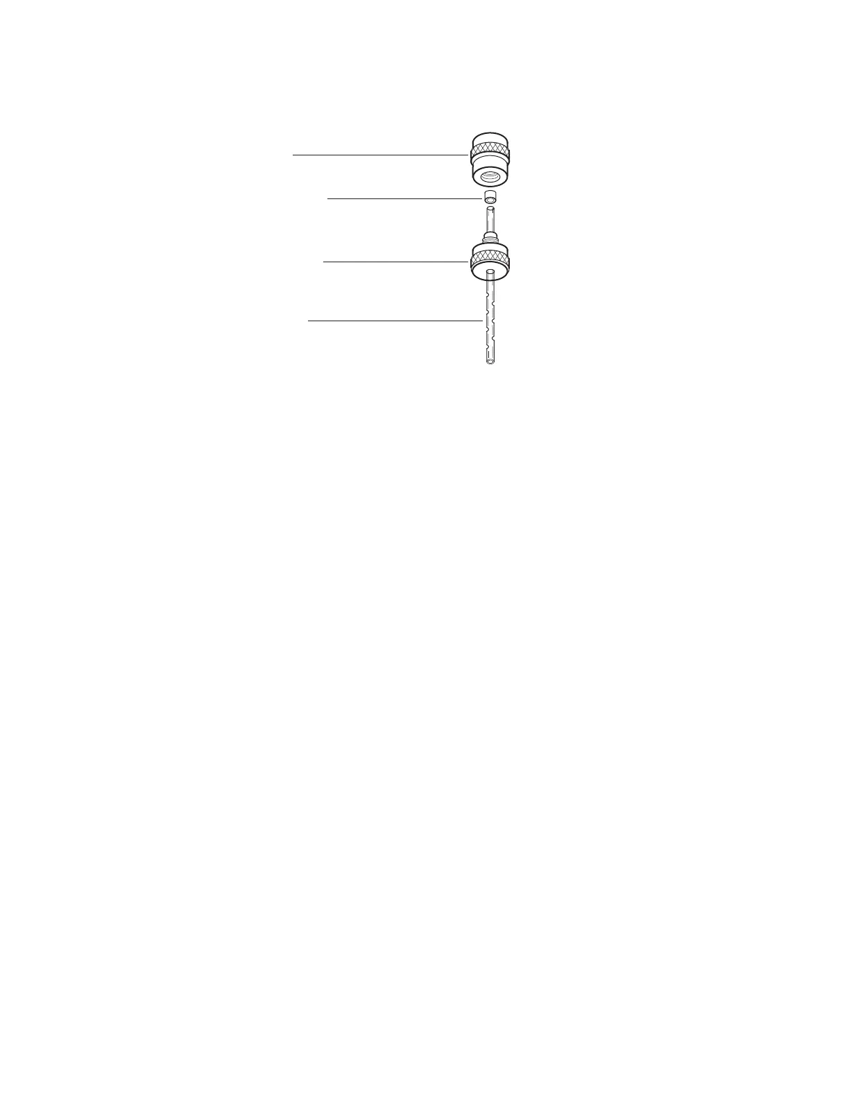
Ferrule guide
Graphpak 3D ferrule
Compression fitting
Open baffle liner

 Loading...


