6 Channel Exchange and Installation
Channel removal procedure
Agilent 990 Micro GC User Manual 87
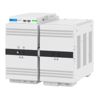
4 Carefully lift and remove main rear cover.
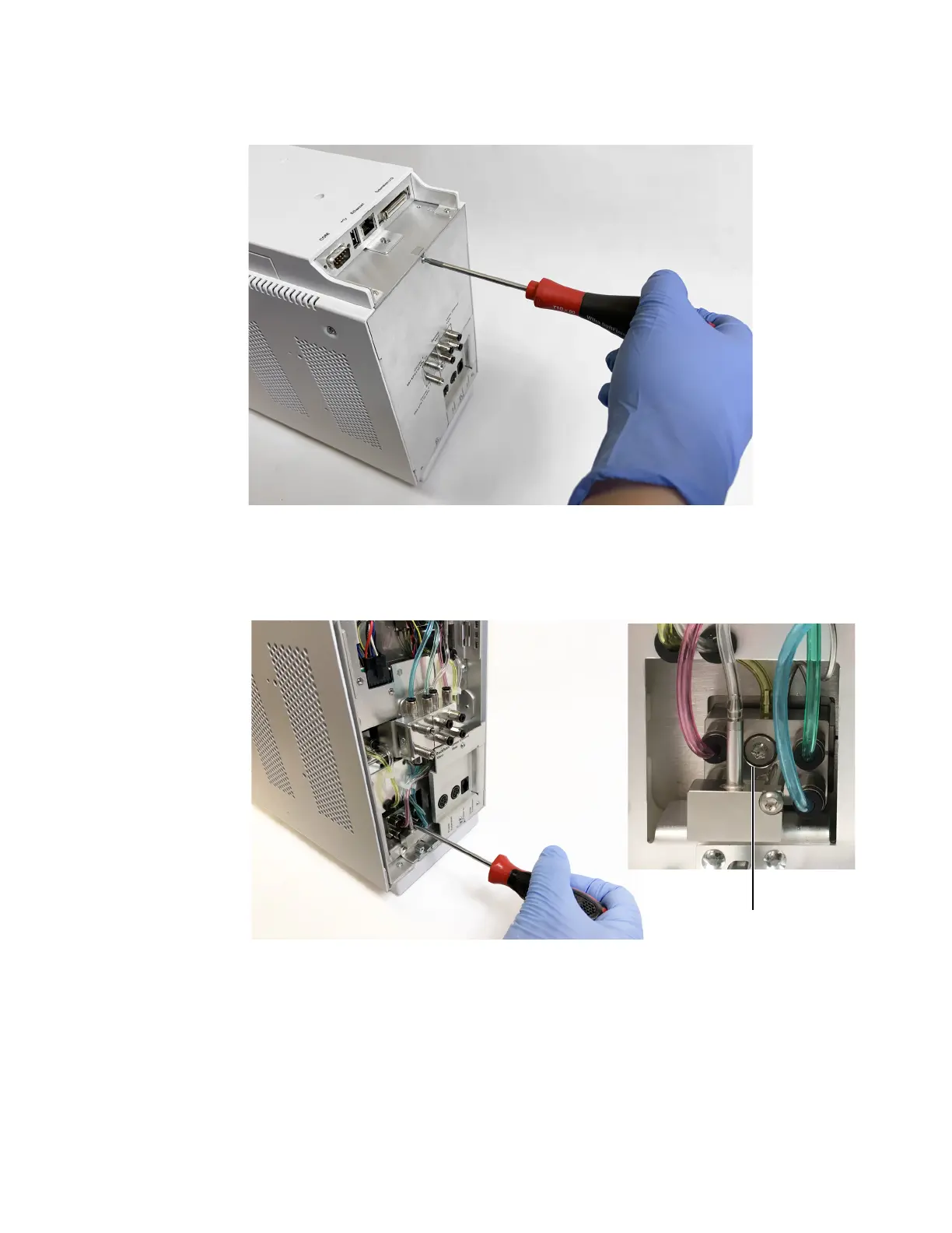
5 Loosen (do not remove) the Torx T-20 screw attaching the Gas Connection Adapter to the
channel you are removing.