4Sample Gas Handling
G3588-68864
Agilent 990 Micro GC User Manual 53
G3588-68864
G3588-68864 provides a pressure regulator and needle valve, along with the required mounting
bracket and hardware required for installation.
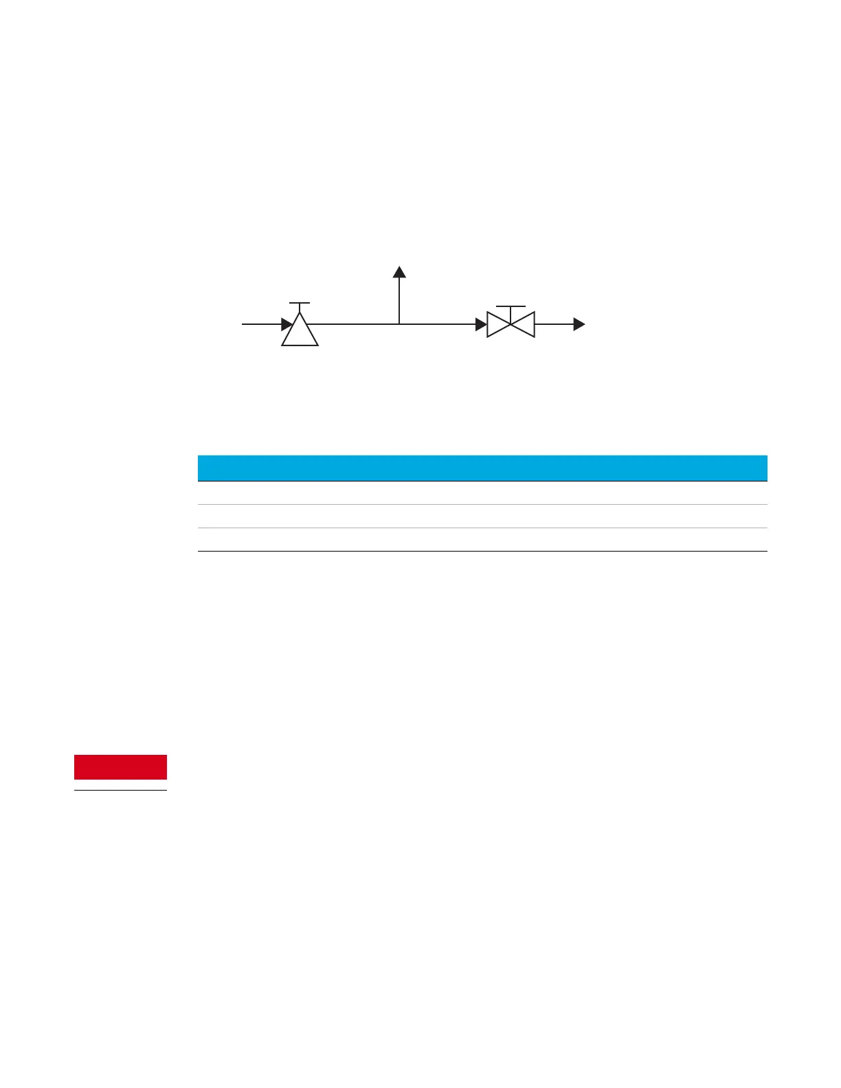
The block diagram below shows the components and connection points for the G3588-68864
pressure regulator assembly.
The pressure regulator has been tested to the fixed specifications shown in Table 10.
The sample flows through the pressure regulator and into the rear sample inlet of the GC.
A needle valve provides for venting the sample for draining.
G3588-68864 Installation
The G3588-68864 pressure regulator assembly is supplied fully assembled and ready to install on
the GC. To install the assembly, do the following:
1 Shut down the GC and allow the column and injector to cool.
See Shut Down Procedure on page 41.
The metal surfaces of the channel and sample inlet can be very hot. Before connecting a tubing
for sample, allow the GC components to cool to ambient temperature.
2 At the front of the GC, disconnect any existing tubing for sample from the sample inlet.
Figure 19. G3588-68864 pressure regulator assembly functional block diagram
Table 10 Pressure regulator specifications
Attribute Specification
Input 25 bar (2.5 Mpa)
Output 0.7 bar (10.1 psi or 70 kPa)
Flow 20 mL/min
Pressure
regulator
Sample
IN
Sample
OUT
(Drain)
Sample to rear sample
inlet of GC
Needle
valve