ESG-D Series Option H98 Signal Generators Using Wideband CDMA
Rear-Panel Overview
Manual Supplement 3-13
12. PATTERN TRIG IN Connector
(System Frame Number Reset In)
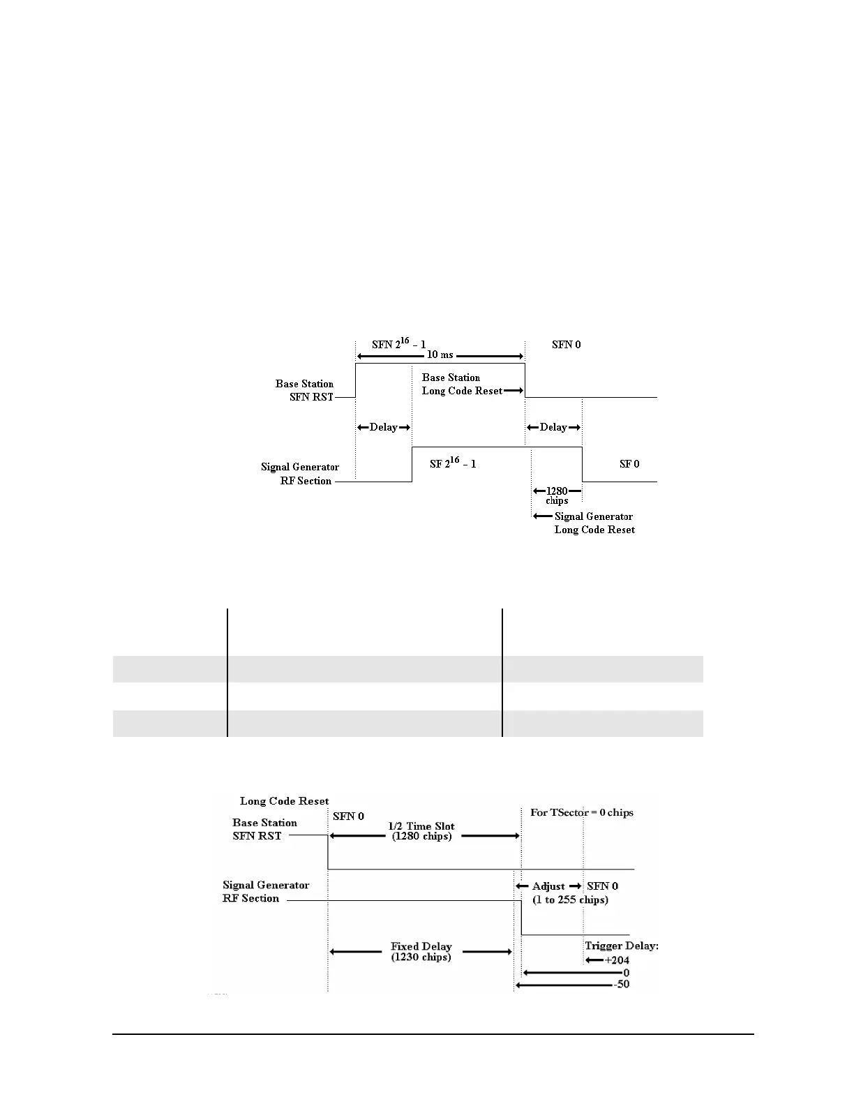
During uplink mode, this input receives the System Frame Number Reset (SFN RST) from
the base station for synchronization. This input is not used during downlink mode.
The instrument triggers on the leading edge of the Base Station SFN RST signal. This
input is a TTL or CMOS signal (not a V.11 signal). The instrument’s 10 MHz reference
input must be locked to the base station’s data recovery reference signal. Note that the
instrument long code is always reset 1280 chips before the first timeslot of system frame 0
(SF0) on the instrument.
Figure 3-5 System Frame Number Reset Input Waveforms
The instrument trigger delay has the affects shown in the following table. These are
approximate propagation delays to within 3 chips.
Figure 3-6 Propagation Delay Timing
Uplink Trigger
Delay Value
Total Propagation Delay Value
(Half Time Slot + Uplink Trigger Delay)
Time Change
(∆ from Half Time Slot)
−50 chips 1280 − 50 = 1230 chips + TSector −12 µs + TSector × 1⁄4.096 MHz
0 chips 1280 + 0 = 1280 chips + TSector
+ TSector × 1⁄4.096 MHz
204 chips 1280 + 204 = 1484 chips + TSector +50 µs + TSector × 1⁄4.096 MHz

 Loading...


