Using Wideband CDMA ESG-D Series Option H98 Signal Generators
Rear-Panel Overview
3-14 Manual Supplement
13. BURST GATE IN Connector (Baseband Gate In)
During downlink mode, a high or open at this input is the normal condition. When a TTL
or CMOS low is detected, the DTCH, Perch1, and Perch2 channels are set to zero power on
the baseband. During uplink mode, this input is left high or open.
15. ALT PWR IN Connector (BCCH Count Hold In)
The normal condition at this input is a high. When a TTL or CMOS low is detected, the
System Frame Number in the Broadcast Control Channel (BCCH) is set and held at zero.
The internal System Frame Number continues to count.
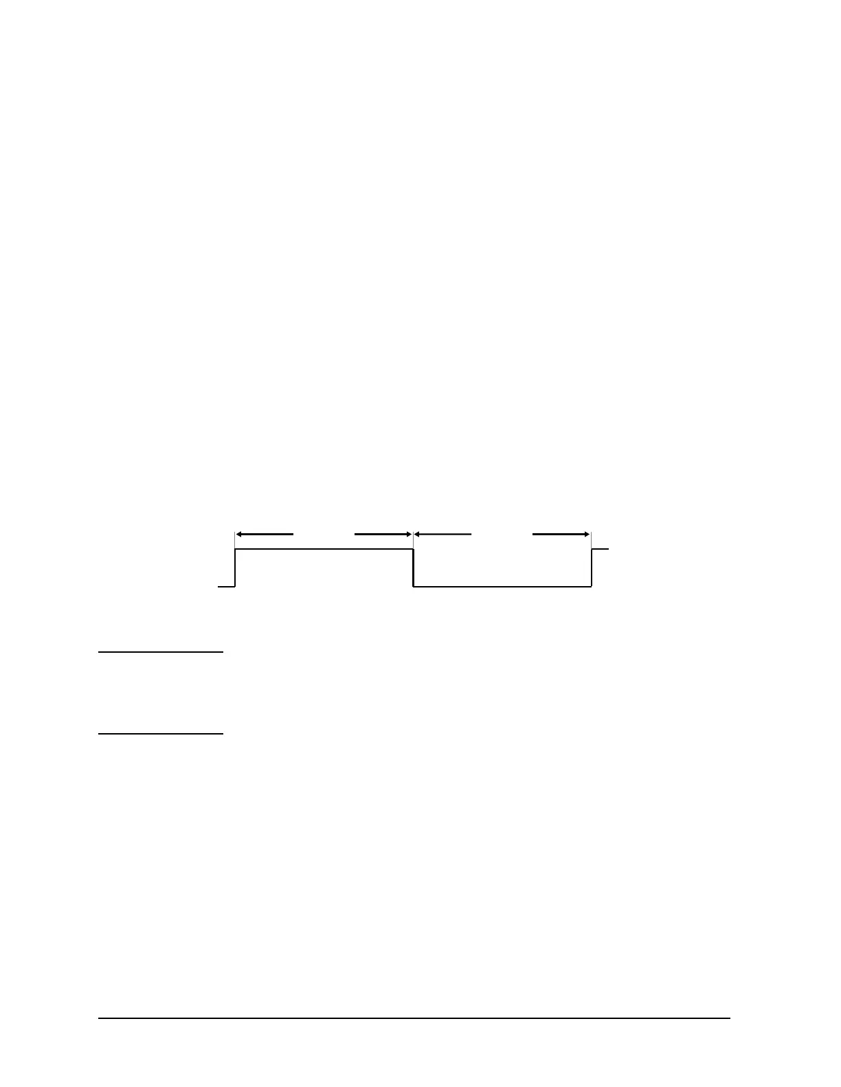
16. EVENT 1 Connector (Frame Sync Out)
This signal alternates between low and high every 10 ms. This signal is high during
odd-numbered frames and low during even-numbered frames.
Figure 3-7 Frame Sync Out Waveform
NOTE The signal edges are referenced to the output of the data generator, not
to the outputs of the baseband generator or the RF section. The delay
from the data generator output to the RF section output is
approximately 24 chips.
10 ms
Odd Numbered SFN Frames Even Numbered SFN Frames
10 ms

 Loading...


