Agilent Technologies Helium Leak Detector
DRAFT 12/11/17
155
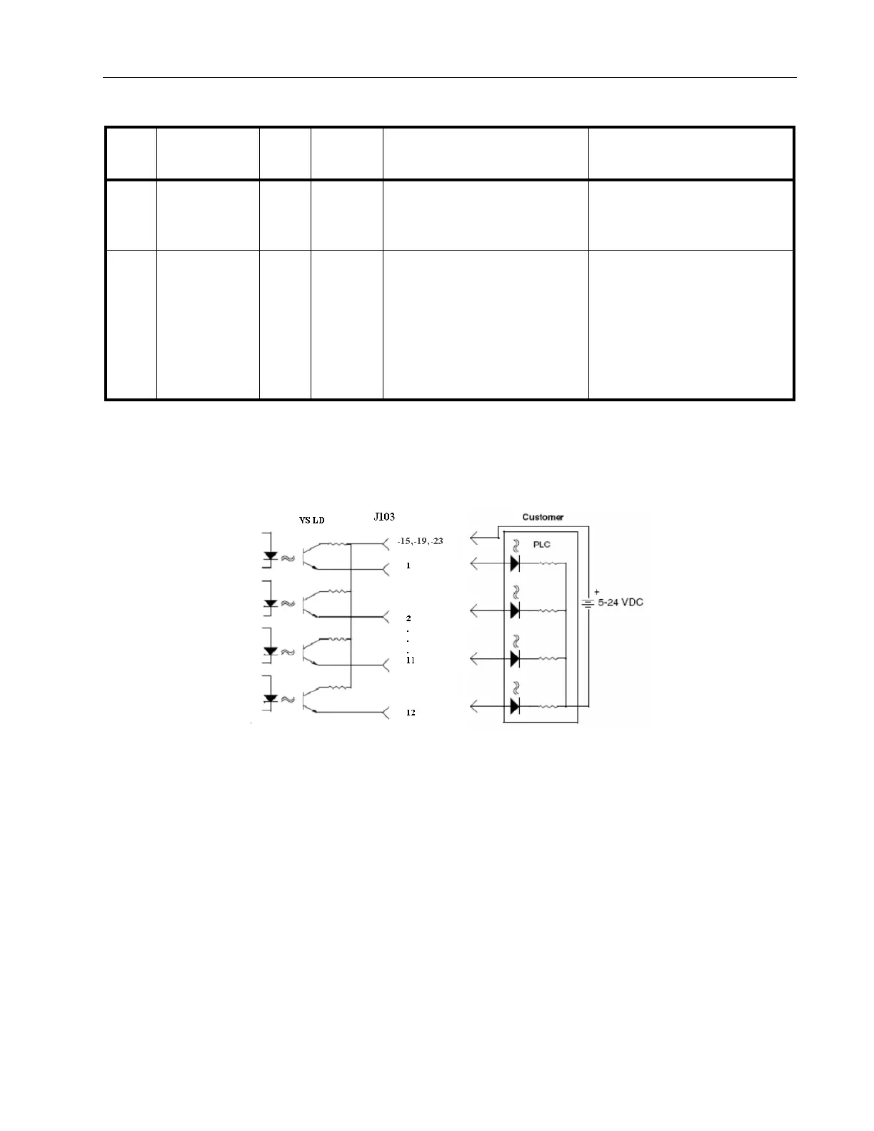
Figure A-2 shows the output circuit sketch. Level outputs are optically isolated emitter
followers with 10 Ohm series resistors, and a 14 mA max drive current (24 VDC max).
Figure A-2 Optically Isolated Output Circuit Sketch
24 RDSTDLK_
IN
I Level Active HIGH when standard
leak is ON.
Initiate the INTERNAL
STANDARD LEAK reading
routine.
25 PARALLEL_
ENABLE_IN
I Level Active HIGH when ENABLE
is active.
Activation causes the leak
detector to take inputs only
from the rear panel I/O or
RS-232 port. No control
functions (inputs) from the
front panel or wireless are
allowed.
Table A-6 I/O Connector Pin Signals (Continued)
Pin
No. Signal Name I/O Signal Description Leak Detector Behavior