Agilent Technologies Helium Leak Detector
DRAFT 12/11/17
53
Section 2. Operating the Leak Detector
2.1 Screens
The leak detector display is used for the initial set-up and configuration of the leak detector.
Once the leak detector is set up and configured for a specific application, basic operation is
controlled primarily using the TEST and VENT buttons on the leak detector and the Home
screen Zero button (Section 3 “Home Screen” on page 55).
2.1.1 Basic Functions
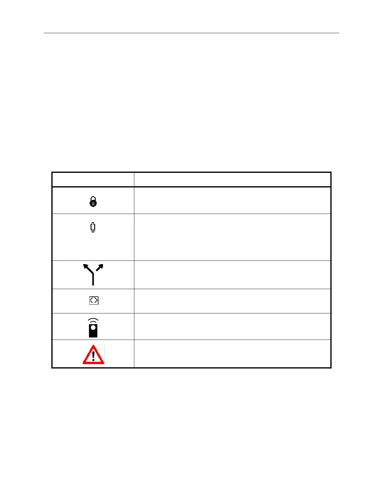
Table 2-1 On-Screen Icons
Icon Meaning
Indicates a feature is locked and cannot be activated due to a
higher level selection in the setup.
Indicates the status of the internal cali
brated leak: If flashing, the
leak calibration will expire within 10 days. Steady and blue
indicates that the leak has expired. Steady and red indicates a
temperature sensor failure or a disconnected cable to the calibrated
leak temperature sensor.
Indicates the leak detector is in split flow.
Indicates that the split flow leak rate being entered is greater than
1
000 times the indicated leak rate; the maximum permitted.
Indicates that the unit is in communication with a wireless remote
unit.
Indicates that the unit has detected a fault condition.
Table 2-1 explains the icons that appear on
various screens and their meaning.