Agilent Technologies Helium Leak Detector
152
DRAFT 12
/11/17
A.3 Customer Accessible Inputs and Outputs
A.3.1 Serial Connector
Table A-5 Serial Connector Summary
Pin EIA Name Description
2 Received Data Data into the leak detector
3 Transmit Data Data out of the leak detector
5 Signal Common RS-232 Ground
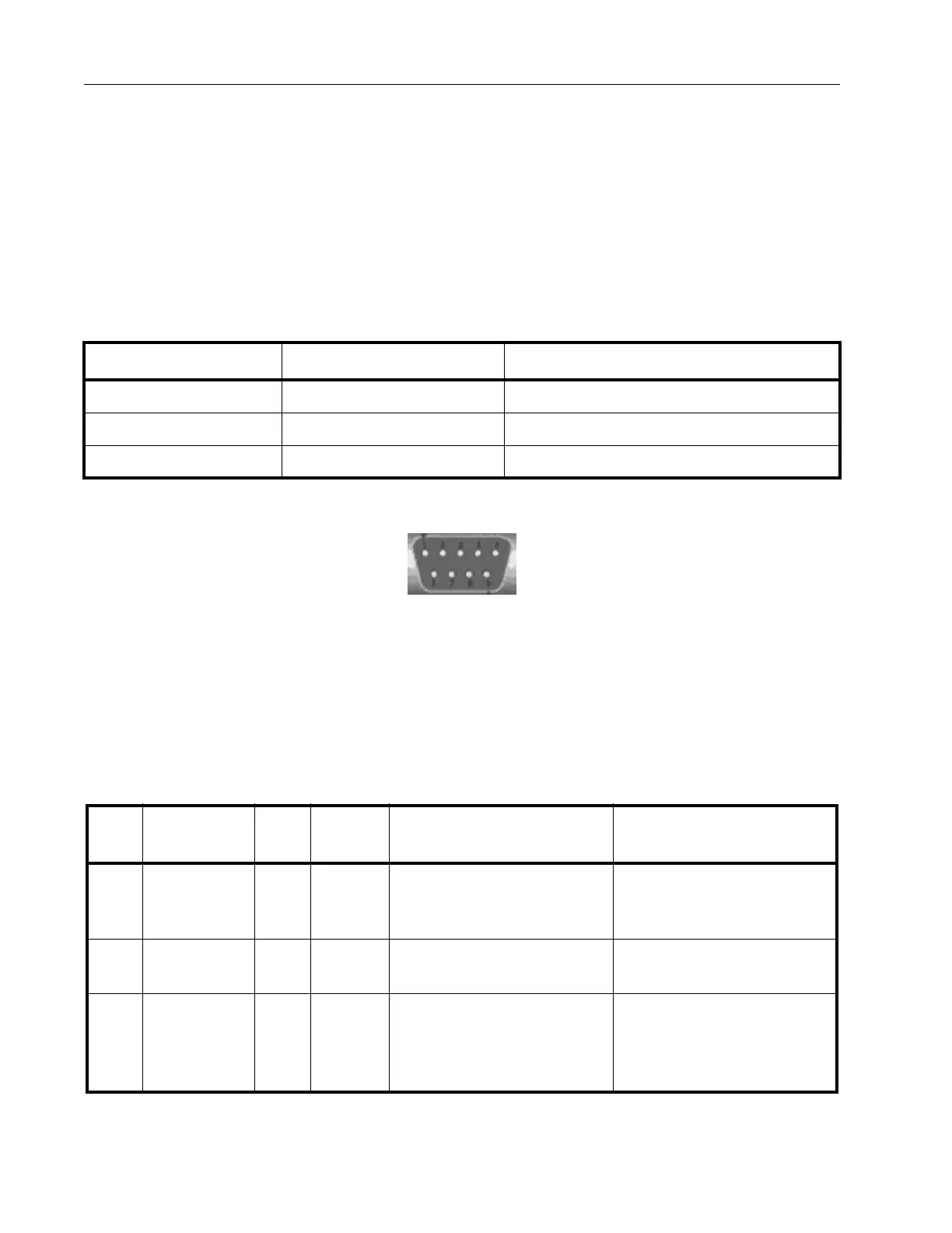
Use the SE
RIAL connector on the Rear Panel to interface the leak detector to a PC via an
isolated RS-232 connection. Table A-5 and Figure A-1 provide details of the connection. A
typical connection from a 9-pin PC serial connector requires a female-to-female, 9-pin, null
modem cable, where pins 2 and 3 are crossed.
Figure A-1 Serial Connector Map
A.3.2 I/O Connector
Table A-6 lists the optional discrete I/O PCB (P/N# R2111501) pin signals. This I/O
connector provides a means for a controller, usually a PLC, to control or to determine the
leak detector status. The I/O is accessible via a type DB25S (female socket) connector.
Table A-6 I/O Connector Pin Signals
Pin
No. Signal Name I/O Signal Description Leak Detector Behavior
15,
19,
23
+ VIN N/A +5 V to
+24
VDC
Customer-supplied +5VDC
to + 24VDC for Output
Common pins.
17,
21
VRET N/A 0 VDC Customer -supplied GND for
t
he Input Common pins.
1 CAL_OUT O Level Active HIGH when the leak
detector is in CALIBRA
TION
mode.
Performs calibrating routine
with the Internal Calibrated
Leak; Zeroing routine is
included.