Introduction 2
Agilent SPS 4 Autosampler User’s Guide 19
Indicator Codes" on Page 66 for details of the various error codes.
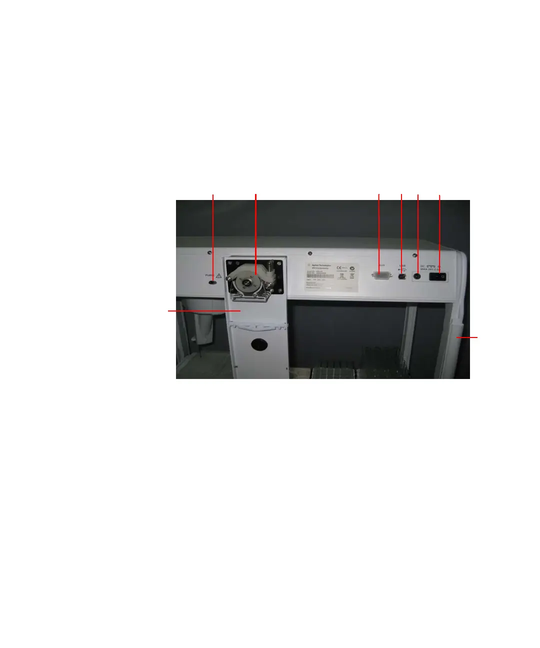
Rear View
Figure 2 shows the rear view of the Agilent SPS 4.
Figure 2 Rear View of Agilent SPS 4
1 Power Switch
The power switch turns on/off the Agilent SPS 4.
I: Power is ON.
O: Power is OFF.
When the Agilent SPS 4 is turned on, the initialization sequence runs to
check the basic functions and set the probe position. If there are no
errors, the power/error indicator turns green.
2 Power Supply Input
The output connector from the AC adapter is connected to this socket.
1
6 5
3 2
7
4
8