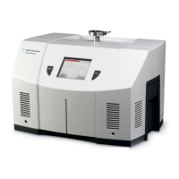
VS Series Helium Mass Spectrometer Leak Detectors
DRAFT 4/23/15
vii
List of Figures
Figure Title Page
1-1 Portable Leak Detector with Internal DS42 Wet Rotary Vane Pump, Model VS PR02, and
Portable Leak Detector with Internal IDP-3 (PD03) Dimensions ........................................ 1-4
1-2 Mobile Leak Detector with External DS302 Wet Rotary Vane Pump on a Cart, Model VS
MR15, Dimensions* ............................................................................................................ 1-4
1-3 Mobile Leak Detector with External TS620 Dry Scroll Pump on a Cart, Model VS MD30+,
Dimensions*........................................................................................................................ 1-5
1-4 Mobile Leak Detector with External IDP-15 Dry Scroll Pump on a Cart, Model VS MD15,
Dimensions*........................................................................................................................ 1-5
1-5 Location of Rear Cover Screws ........................................................................................ 1-11
1-6 Cover Bolts ....................................................................................................................... 1-12
1-7 TriScroll Shipping Bolt....................................................................................................... 1-13
1-8 Cover Bolts ....................................................................................................................... 1-13
1-9 TriScroll Shipping Bolt....................................................................................................... 1-14
1-10 Bench Mount Leak Detector with External DS302 Wet Rotary Vane Pump, Model VS BRI5 .
1-15
1-11 Bench Mount Leak Detector with External TS620 Dry Scroll Pump, Model VS BD30+.... 1-15
1-12 Bench Mount Leak Detector with External IDP-15 Dry Scroll Pump, Model VS BD15 ..... 1-16
1-13 Front Panel Displays and Controls ................................................................................... 1-18
1-14 Screen Flow ...................................................................................................................... 1-21
1-15 VS Series Rear Panel .......................................................................................................1-24
1-16 Optional I/O PCB Rear Panel ........................................................................................... 1-25
1-17 Rear Panel (with Discrete I/O PCB).................................................................................. 1-27
2-1 Helium Background Timer .................................................................................................. 2-2
2-2 Home Screen ...................................................................................................................... 2-7
2-3 Gross Test Screen .............................................................................................................. 2-9
2-4 Control Panel .................................................................................................................... 2-12
2-5 20 Minute Warm-up Dialog ............................................................................................... 2-14
2-6 Graphical Display.............................................................................................................. 2-15
2-7 Menus Screen................................................................................................................... 2-16
2-8 Calibration Set-Up............................................................................................................. 2-17
2-9 Helium Background Timer ................................................................................................ 2-18
2-10 Reject and Audio Setpoints............................................................................................... 2-19
2-11 Auto Sequencer ................................................................................................................ 2-23
2-12 Leak Rate Ranging ...........................................................................................................2-25
2-13 Transfer Points.................................................................................................................. 2-28
2-14 Transfer Points with Stabilization Wait Timer ................................................................... 2-29
2-15 System Information ........................................................................................................... 2-30
2-16 Control Panel Access........................................................................................................2-32
3-1 Set-Up Screen - Initial......................................................................................................... 3-1
3-2 Set-Up Screen - Second ..................................................................................................... 3-2
3-3 Advanced Parameters ........................................................................................................ 3-3
3-4 Manual Tuning .................................................................................................................... 3-7

 Loading...