VS Series Helium Mass Spectrometer Leak Detectors
3-10
DRAFT 4/
23/15
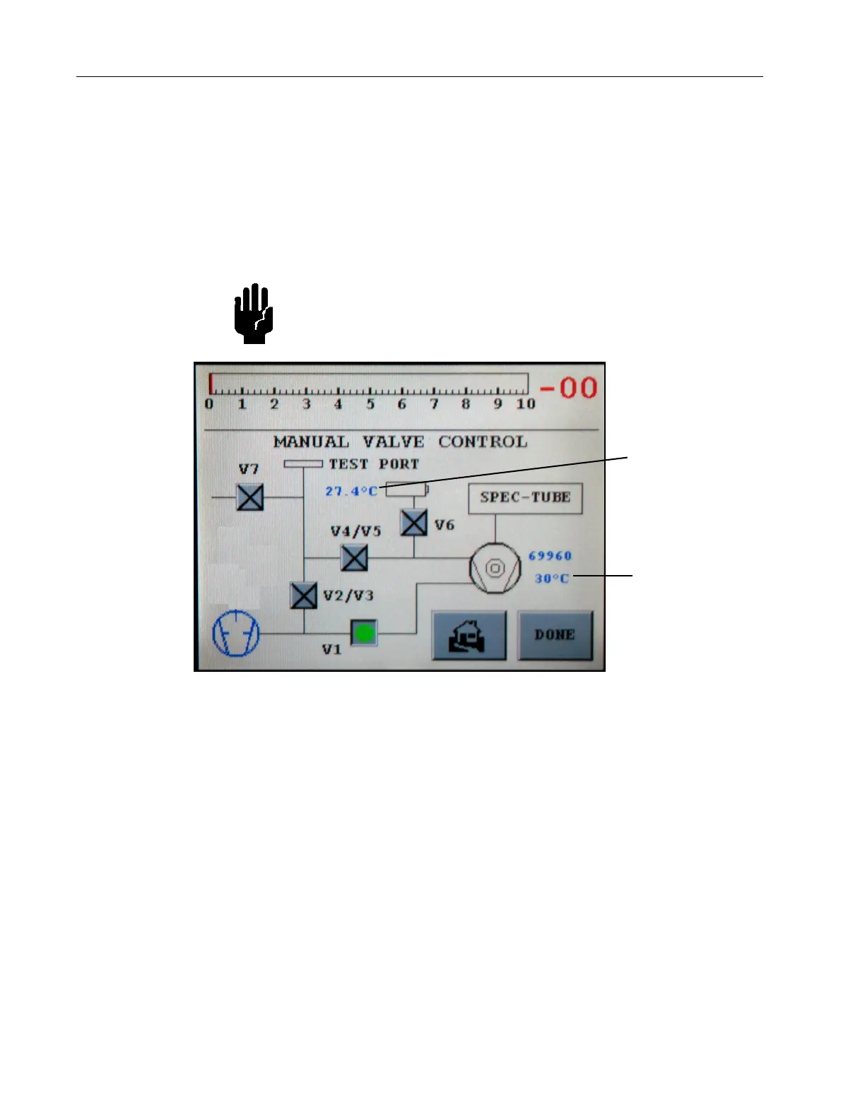
3.1.3 Manual Valve Control
❑ Press Valve Control on the Set-Up screen and the Manual Valve Control screen
appears (
Figure 3-5).
Use this screen to manually control the valves in the leak detector vacuum system
for troubleshooting purposes.
See Figure 3-7 on page 3-12 for an illustration of the leak detector vacuum system.
CAUTION Manipulation of the valves using the Manual Valve Control
screen must only be performed by persons who are extremely
familiar with the leak detector as damage to critical
components (e.g., spectrometer, turbo) could occur.
Figure 3-5 Manual Valve Control
❑ Press the box corresponding to that valve to change the state of a specific valve.
The valve changes state and the box toggles from an X indication (CLOSED) to a
Green Circle (OPENED).
The valve state (displayed to the right of each valve control box) represents the
current state of the corresponding valve. The normal operating states of valves for
single mechanical pump systems are provided in Table 3-1 on page 3-12.
Turbo bear in g
temperature
Calibrated leak
temperature
 Loading...