Publication 1762-UM001D-EN-P - March 2004
F-2 System Loading and Heat Dissipation
Validating the System
The example systems shown in the tables below are verified to be
acceptable configurations. The systems are valid because:
• Calculated Current Values < Maximum Allowable Current
Values
• Calculated System Loading < Maximum Allowable System
Loading
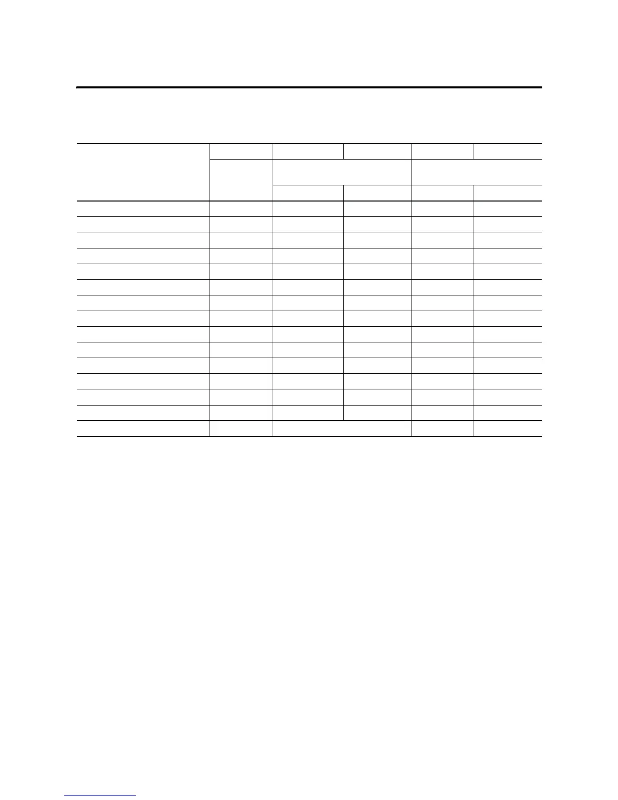
Table F.2 Calculating the Current for Expansion I/O
Catalog Number
(1)
n A B n x A n x B
Number of
Modules
Device Current Requirements
(max)
Calculated Current
at 5V dc (mA) at 24V dc (mA) at 5V dc (mA) at 24V dc (mA)
1762-IA8 2 50 0 100 0
1762-IF4 40 50
1762-IF2OF2 40 105
1762-IQ8 50 0
1762-IQ16 60 0
1762-IR4 40 50
1762-IT4 40 50
1762-OA8 115 0
1762-OB8 115 0
1762-OB16 175 0
1762-OF4 40 165
1762-OW8 2 80 90 160 180
1762-OW16 120 140
1762-OX6I 110 110
Total Modules (6 maximum): 4 Subtotal 2: 260 180
(1) Refer to your expansion I/O Installation Instructions for Current Requirements not listed in this table.

 Loading...


