EasyManuals Logo

Allen-Bradley MicroLogix 1200 User Manual

Allen-Bradley MicroLogix 1200
162 pages
To Next Page IconTo Next Page
To Previous Page IconTo Previous Page
Page #32 background imageLoading...
Page #32 background image
Publication 1762-UM001D-EN-P - March 2004
2-16 Installing Your Controller
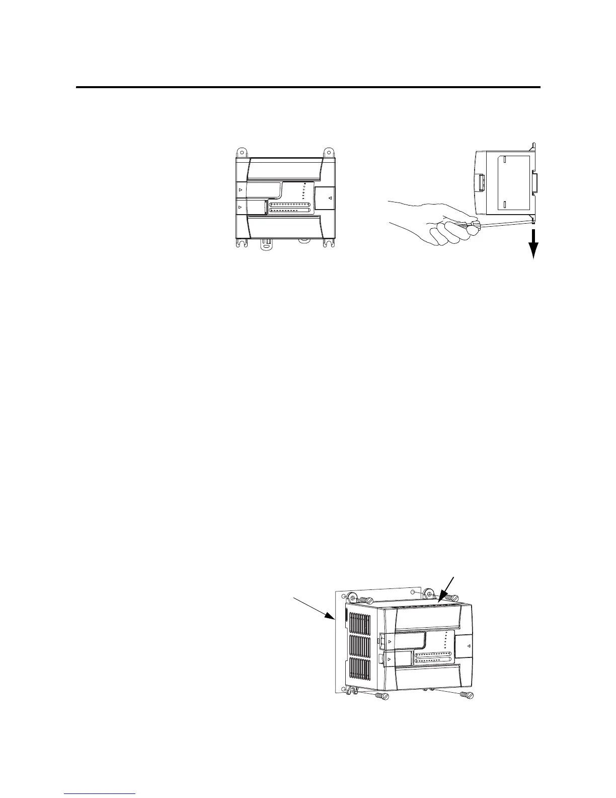
4. Unhook the top of the DIN rail slot from the rail.
Panel Mounting
Mount to panel using #8 or M4 screws. To install your controller using
mounting screws:
1. Remove the mounting template from inside the back cover of
the MicroLogix 1200 Programmable Controllers Installation
Instructions, publication 1762-IN006.
2. Secure the template to the mounting surface. (Make sure your
controller is spaced properly. See Controller and Expansion I/O
Spacing on page 2-13.)
3. Drill holes through the template.
4. Remove the mounting template.
5. Mount the controller.
6. Leave the protective debris shield in place until you are finished
wiring the controller and any other devices.
open
closed
Mounting Template
Debris Shield

Table of Contents

Other manuals for Allen-Bradley MicroLogix 1200

Questions and Answers:

Question and Answer IconNeed help?

Do you have a question about the Allen-Bradley MicroLogix 1200 and is the answer not in the manual?

Allen-Bradley MicroLogix 1200 Specifications

General IconGeneral
SeriesMicroLogix 1200
TypeProgrammable Logic Controller (PLC)
MountingDIN rail or panel mount
Programming LanguageLadder Logic
Programming SoftwareRSLogix 500
I/O PointsUp to 40
Communication PortsRS-232, RS-485
Memory6 KB user memory
Power Supply24V DC or 120/240V AC
ExpansionSupports expansion I/O modules
Operating Temperature0°C to 55°C (32°F to 131°F)
Dimensions90 mm x 110 mm
Weight0.5 kg (1.1 lbs)

Related product manuals