1 Publication 1762-UM001D-EN-P - March 2004
Chapter
6
Using Real-Time Clock and Memory Modules
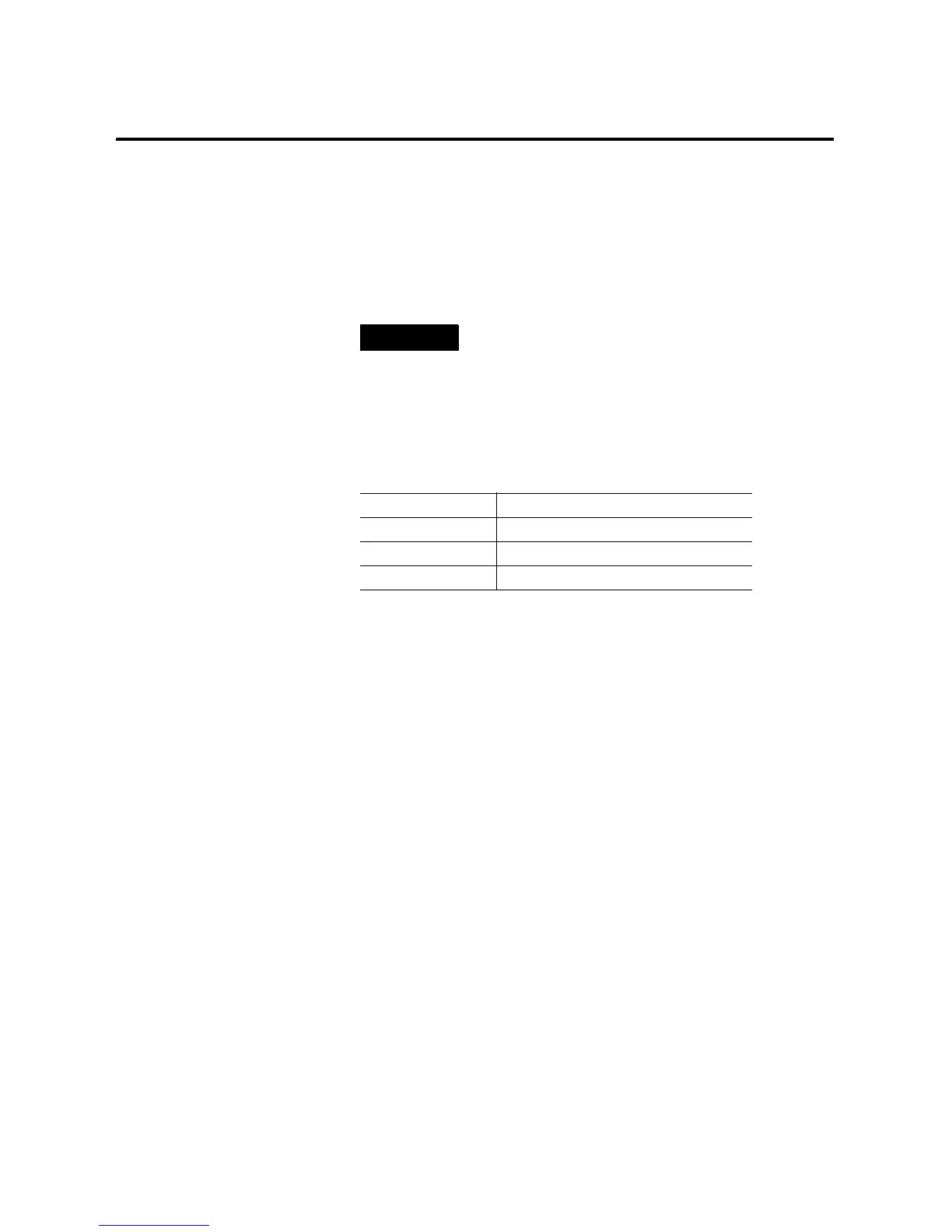
Three modules with different levels of functionality are available for
use with the MicroLogix 1200 controller.
Real-Time Clock Operation
Removal/Insertion Under Power
At power-up and when the controller enters a run or test mode, the
controller determines if a real-time clock module (RTC) is present. If
an RTC is present, its values (date, time and status) are written to the
RTC Function File in the controller.
The RTC module can be installed or removed at any time without risk
of damage to either the module or the controller. If an RTC is installed
while the MicroLogix 1200 is in a run or test mode, the module is not
recognized until either a power cycle occurs or until the controller is
placed in a non-executing mode (program mode, suspend mode or
fault condition).
Removal of the RTC during run mode is detected within one program
scan. Removal of the RTC while in run mode causes the controller to
write zeros to the RTC Function File.
The following table indicates the accuracy of the RTC for various
temperatures.
TIP
For more information on “Real-Time Clock Function
File” and “Memory Module Information File” refer to
the MicroLogix 1200 and 1500 Programmable
Controllers Instruction Set Reference Manual,
publication 1762-RM001.
Catalog Number Function
1762-RTC Real-Time Clock
1762-MM1 Memory Module
1762-MM1RTC Memory Module and Real-Time Clock

 Loading...


