Publication 1762-UM001D-EN-P - March 2004
4-18 Communication Connections
Installing and Attaching the AIC+
1. Take care when installing the AIC+ in an enclosure so that the
cable connecting the MicroLogix 1200 controller to the AIC+
does not interfere with the enclosure door.
2. Carefully plug the terminal block into the RS-485 port on the
AIC+ you are putting on the network. Allow enough cable slack
to prevent stress on the plug.
3. Provide strain relief for the Belden cable after it is wired to the
terminal block. This guards against breakage of the Belden cable
wires.
Powering the AIC+
In normal operation with the MicroLogix 1200 programmable
controller connected to port 2 of the AIC+, the controller powers the
AIC+. Any AIC+ not connected to a controller requires a 24V dc
power supply. The AIC+ requires 120 mA at 24V dc.
If both the controller and external power are connected to the AIC+,
the power selection switch determines what device powers the AIC+.
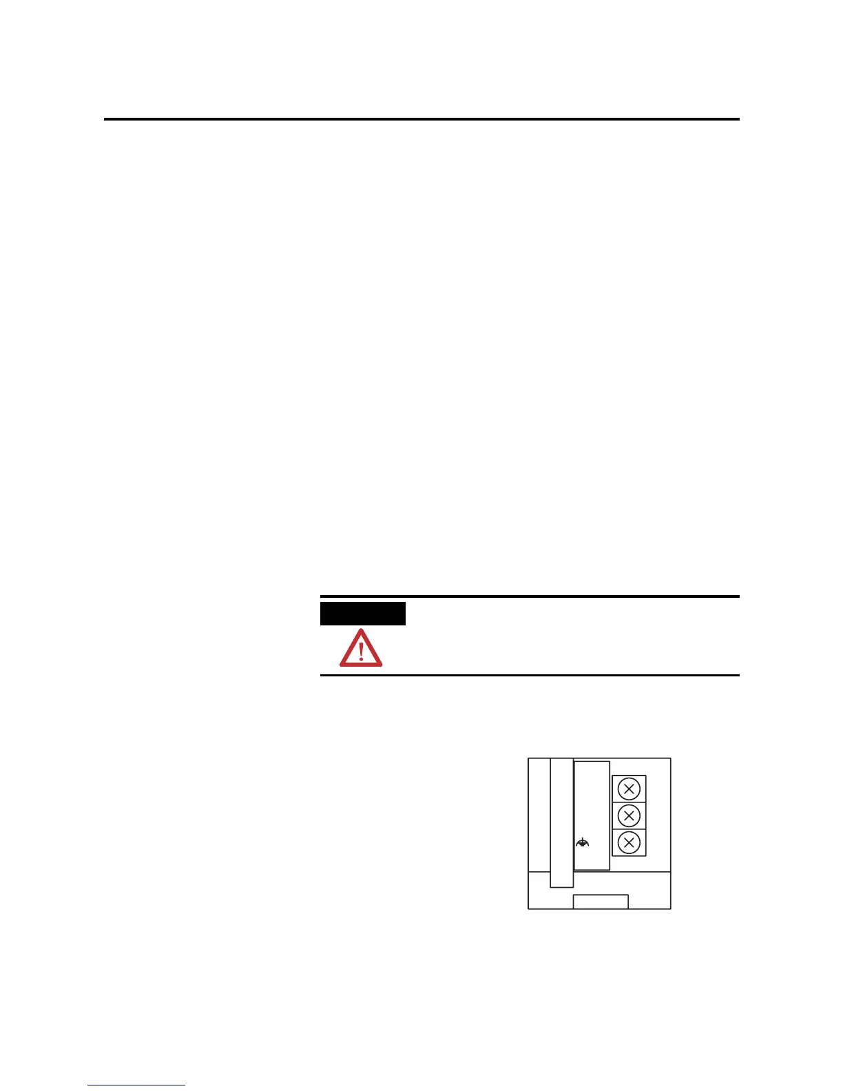
Set the DC Power Source selector switch to EXTERNAL before
connecting the power supply to the AIC+. The following illustration
shows where to connect external power for the AIC+.
ATTENTION
If you use an external power supply, it must be
24V dc (-15%/+20%). Permanent damage results if a
higher voltage supply is used.
24VDC
DC
NEUT
CHS
GND
Bottom View

 Loading...


